


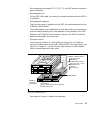
Router Node 31
6. The packet is then transferred to the Combus interface by the DMA
engine.
7. The packet is sent to the IP Switch Control Board’s Router Manager
across the Combus.
8. The Route Manager receives the packet and passes it to the dynamic
routing software.
9. The packet is processed and global routing information is determined.
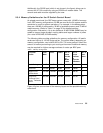
10.Route updates are broadcast across the Combus to all media cards
simultaneously.
11.Each card receives the update packet and makes changes to its route
tables.
12.The packet is transferred across the media.
To ensure that dynamic routing packets are not dropped during times of
heavy congestion, precedence features are used. Routing packets are given
a high-priority tag and a user-configurable threshold for Tx buffers is
maintained for high-priority traffic.
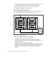
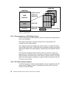
2.3.3 IP Switch and Control Board
The control board, also known as the IP Switch Control Board, is accessed
through Telnet or a locally attached VT100 terminal. The IP Switch Control
Board is supplied with the GRF and is necessary for its operation. The VT100
terminal is not supplied with the GRF. It is only needed for the installation of
the GRF.
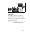
Using terminal emulation software instead of looking for a real VT 100
terminal may be an alternative. You can use your Control Workstation or one
of your SP nodes. Install the
ATE
package (advanced terminal emulation) on
your RS/6000 and establish a serial connection between the system and the
router.
After installation, all future access to the GRF can be through Telnet to the IP
Switch Control Board’s administrative Ethernet.
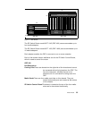
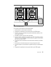
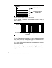
The IP Switch Control Board is identified as slot 66 in both GRF models. A
sideview of the GRF 400 slot numbering scheme is shown in Figure 15 on
page 32.