


© Copyright IBM Corp. 1998 203
Chapter 6. Multiple RS/6000 SPs and One SP Switch Router
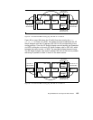
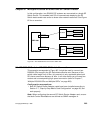
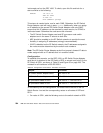
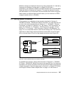
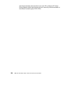
In this configuration, two RS/6000 SP systems are connected to a single SP
Switch Router. This enables both SPs to communicate deploying the SP
Switch data transfer rate and/or to share other network resources. See Figure
65 for an overview.
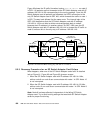
Figure 65. Two RS/6000 SPs Connected to GRF 1600
6.1 RS/6000 SP Switch - RS/6000 SP Switch Connection
This scenario corresponds to Figure 65. It might be used to connect two
RS/6000 SPs to exploit the SP Switch data transfer rate. Because of the
switch cable length limit of 20m, this scenario is only applicable when both
SPs have a maximum distance of 40m. In all other cases you will need two
routers and a corresponding high speed connection (refer to Chapter 7,
“Multiple RS/6000 SPs and Multiple GRFs” on page 209).
Configuration assumptions:
• Both SP Switch Router Adapter cards have been installed according to
Section 3.7, “Step-by-Step Media Card Configuration” on page 86, and
work properly.
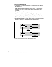
Note:
When configuring the second SP Switch Router Adapter card, ensure
that
both
Control Workstations are defined as SNMP managers in
SP Switch
SP processor node
SP processor node
partition
SP Switch
SP processor node
SP processor node
partition
GRF 1600
SP Switch Router
Adapter card 2
SP Switch Router
Adapter card 1
SP 21
SP 2