


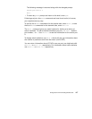

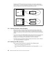


Configuration of IP-Forwarding Media Cards 125
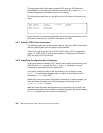
super> write
CARD/0 written
super>
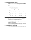
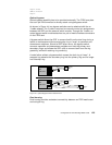
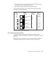
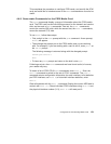
Optical bypass
Optical bypass capability has to be provided externally. The FDDI face plate
has a six-pin DIN connector to directly attach a single bypass switch.
As shown in Figure 44, two bypass switches can be attached with the an
Y-cable adapter. The Y-cable is required to reconcile control pin assignments
between the GRF and the external switch module. Through the Y-cable, an
optical bypass switch module attaches to a pair of media interface connectors
on the FDDI card.
A bypass switch allows the GRF to remove itself from the dual ring during a
failure or maintenance without causing the ring to "wrap" at upstream and
downstream neighbors. Should a GRF failure occur, the bypass switch
connects upstream and downstream neighbors on both the primary and
secondary rings, and allows the GRF node to remove itself from the ring
gracefully, while still retaining ring continuity.
A node failure without a bypass switch causes the dual ring to "wrap". A
wrapped ring absorbs the secondary ring into the primary ring and no longer
has a backup ring.
Figure 44. Optical Bypass Switch Attachments
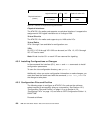
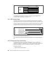
Dual homing
Dual homing provides redundant connectivity between an FDDI media card
and a single ring.
FDDI
media card
Ring 1
Switch Module
Switch Module 2
Switch Module 1
Ring 2
Ring 1
FDDI
media card