


34 IBM 9077 SP Switch Router: Get Connected to the SP Switch
ItemDescription
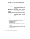
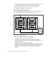
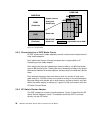
MemoryThe IP Switch Control Board comes standard with 128 MB of
memory (the four shaded blocks of 32 MB of
memory in the upper left corner).
The memory can be upgraded to 256 MB, in increments of 64 MB (the four
white blocks of memory).
The system uses the first 32 MB of memory for file system storage. The
top half is used for applications such as the SNMP
agent, the gated daemon, and for the operating
system.
Flash memoryThis memory (the 85 MB ATA flash memory on the system) is
used to store the operating system information
and the configuration information for the GRF.
System busThis bus is used by the IP Switch Control Board components to
communicate with each other.
Pentium processorThis 166 MHz processor drives the IP Switch Control
Board and the GRF. As previously mentioned, this
processor runs a variant of BSD UNIX, and so it is
useful for the GRF administrator to have UNIX
management skills.
Administrative EthernetThis Ethernet is known to the GRF as de0. This port
supports the 10BaseT or the 100BaseT Ethernets
and switches between them automatically,
depending on the type of network used.
To use 10Base2 or 10Base5, the user must add a transceiver (supplied by
the user).
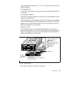
PCMCIA cardsThe two white blocks at the bottom right corner of the figure
are PCMCIA slots.
There are two types of PCMCIA cards:
• Slot A on the 9077 is configured with a 520 MB disk drive. This disk is
used to hold the log of the GRF. It may also be
used to backup the configuration of the GRF.
Making a backup is strongly recommended.
• The PCMCIA modem card, also available as an optional device, allows
the user to dial into the GRF through a modem
to administer it remotely.
Note: For the initial setup, the console must be available locally, not
through the modem.