


Single RS/6000 SP and Single SP Switch Router 181
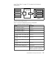
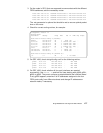
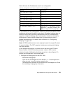
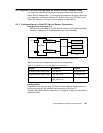
Table 18 shows the IP addresses used in our configuration.
Table 18. Configuration of SP Switch - FDDI Connection (Bridging)
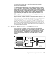
To successfully run this configuration, make sure that all four different FDDI
backbones are logically located in one subnet. Otherwise, bridging does not
work and routing has to be used. Nevertheless, the GRF simultaneously
supports routing and bridging which means that an interface included in a
bridge group is able to handle bridge layer-2 frames and route layer-3
packets simultaneously. For details, refer to Section 4.6, “Configuring
Bridging” on page 142.
Note:
All FDDI backbones have to be logically located in a single IP subnet
for proper bridging. The GRF supports simultaneous routing and bridging
over one interface.
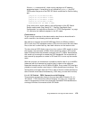
In this sample configuration, no routes need to be set on the SP Switch
Router. Node 9-12 on SP2 and the processor nodes in SP21 require
attention, though. Additionally, the bridge group has to be configured. To
perform this configuration, follow these steps:
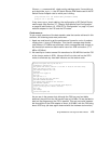
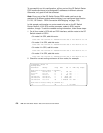
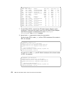
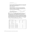
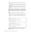
1. Configure the bridge group on the GRF 1600.
• Define the bridge group:
Open the file /etc/bridged.conf with bredit or vi
. If /etc/bridged.conf
does not exist, a new file can be created or the
/etc/bridged.conf.template can be renamed to /etc/bridged.conf. Enter
the necessary bridge group information:
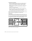
Adapter IP Address
FDDI interface in node 9 10.10.1.9
FDDI interface in node 10 10.10.1.10
FDDI interface in node 11 10.10.1.11
FDDI interface in node 12 10.10.1.12
Bridge Group bg0 10.10.1.13
SP Switch Router Adapter card 1 192.168.14.4
SP processor nodes in SP21
192.168.14.1 - 192.168.14.15
(See
Appendix A, “Laboratory Hardware and
Software Configuration” on page 233.)