


184 IBM 9077 SP Switch Router: Get Connected to the SP Switch
7. On the CWS of SP21, check if the SP Switch Router Adapter card is
configured. To perform this check, look if the SP Switch Router Adapter
card shows up green in perspectives or enter
SDRGetObjects
switch_responds
. Use Eunfence if needed.
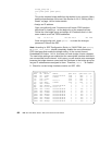
8. Issue some
ping commands to check the connection:
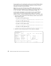
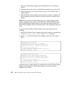
On the chosen SP21 nodes,
ping all four FDDI interfaces of nodes in SP2,
for example:
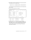
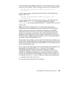
On node 9-12 in SP2,
ping the SP Switch interfaces of the chosen nodes
in SP21, for example:
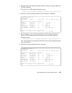
If these
ping commands fail, check routing settings, bridging settings and
IP address assignment again. If everything is as it should be, try to
ping
the bridge group and the SP Switch Router media card to find the failing
part:
ping 10.10.1.13 (on nodes 9-12 in SP2)
ping 192.168.14.4 (on nodes in SP21)
If any errors occur, check cabling, the configuration of SP the Switch
Router media cards (See Section 3.7, “Step-by-Step Media Card
Configuration” on page 86 and Section 4.4, “FDDI Configuration” on page
121) and also the network adapters in the nodes.
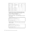
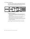
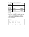
Performance:
To get a rough overview of the data transfer rates that can be achieved in
such a bridging scenario, we again used ftp to transfer several 300 MB files
from different nodes in SP21 to the four FDDI-equipped nodes in SP2 and
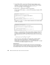
root@sp21n01:/ ping 10.10.1.9
PING 10.10.1.9: (10.10.1.9): 56 data bytes
64 bytes from 10.10.1.9: icmp_seq=0 ttl=254 time=2 ms
64 bytes from 10.10.1.9: icmp_seq=1 ttl=254 time=1 ms
^C
----10.10.1.9 PING Statistics----
2 packets transmitted, 2 packets received, 0% packet loss
round-trip min/avg/max = 1/1/2 ms
root@sp2n12:/ ping 192.168.14.1
PING 192.168.14.1: (192.168.14.1): 56 data bytes
64 bytes from 192.168.14.1: icmp_seq=0 ttl=254 time=1 ms
64 bytes from 192.168.14.1: icmp_seq=1 ttl=254 time=1 ms
^C
----192.168.14.1 PING Statistics----
2 packets transmitted, 2 packets received, 0% packet loss
round-trip min/avg/max = 1/1/1 ms