


Configuration of IP-Forwarding Media Cards 111
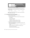
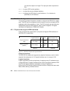
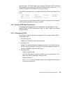
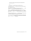
See Figure 38 for the naming conventions of an ATM interface.
Figure 38. Components in the ATM OC-3c Interface Name
Virtual Circuits
A virtual circuit (VC) exists between two ATM devices. It is the point-to-point
connection between them and is of no significance to other ATM devices.
Each VC is identified by a pair of numbers, representing a virtual path
identifier (VPI) and a virtual circuit identifier (VCI). A slash (/) is used to
separate the two numbers, for example, 0/2645. The VPI/VCI must be unique
on a link. Because it is acceptable to use the same VPI/VCI on different links,
a GRF can have the same VPI/VCI active on each physical interface.
The ATM OC-3c media card supports up to 1024 active VCs as defined in the
ATM Forum UNI3.0 specification. VCs can be divided between the two
physical interfaces in any manner required by the site, with 512 VCs active at
any one time on each interface. Each VC has an associated IP address.
VPI/VCIs are assigned to logical interfaces in /etc/gratm.conf, and provide the
bridge between ATM and IP.
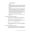
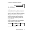
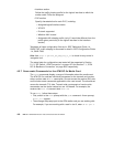
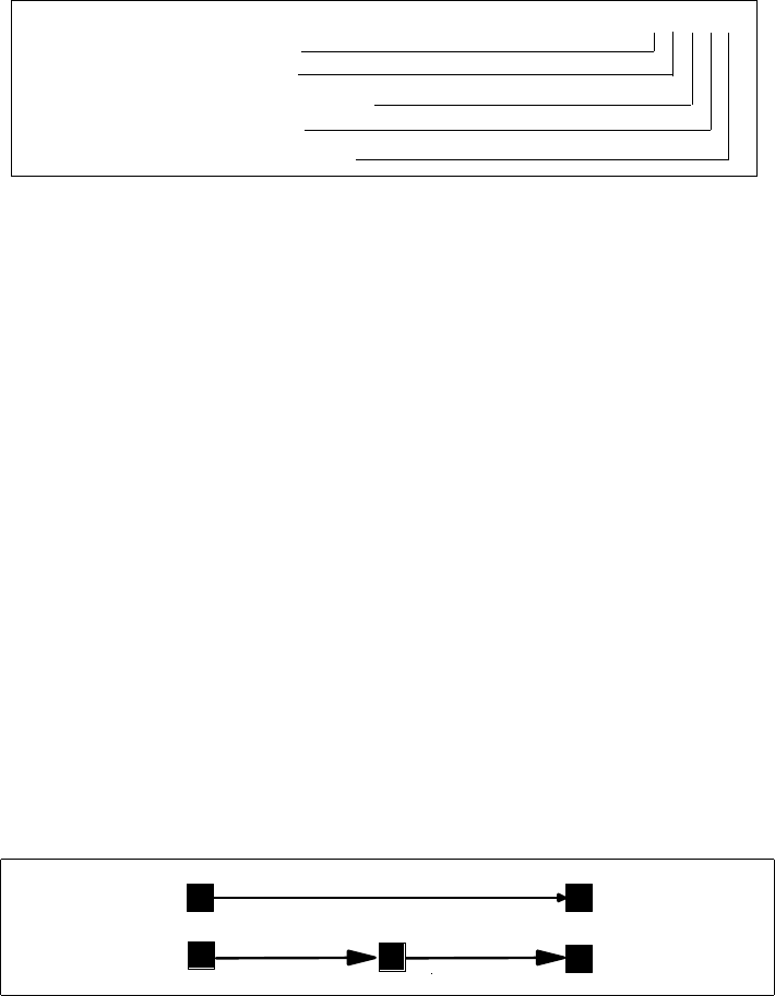
Virtual Paths
A virtual path (VP) connects two end stations, which may be separated by
one or more network devices such as a router or switch. A path consists of
one or more virtual circuits, as you can see in Figure 39.
Figure 39. Components Forming a Virtual Path
2nd: media type, a (ATM)
1st: always "g" for GRF
3rd: chassis number, always "0" (zero)
4th: slot number in hex
5th-6th: logical interface number in hex
g a 0 x yz
Virtual Path
Virtual
Circuit Circuit
Virtual