


TROUBLESHOOTING & REPAIR
F-45 F-45
COMMANDER 300
Return to Section TOC Return to Section TOC Return to Section TOC Return to Section TOC
Return to Master TOC Return to Master TOC Return to Master TOC Return to Master TOC
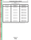
RF BY-PASS BOARD RESISTANCE TEST (continued)
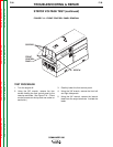
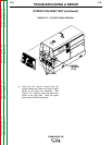
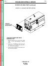
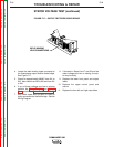
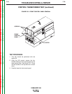
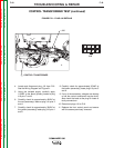
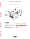
FIGURE F.19 – RF BY-PASS BOARD
J61
J62
J60
ARA
4. Locate, label, and remove the three plugs
from the RF By-Pass board. See Figure 19.
5. Using the phillips head screwdriver, remove
the three mounting screws from the board.
NOTE: Take note of the screw and washer place-
ment for reassembly.
6. Using the ohmmeter, check for the correct
resistance readings per Table F.1. If any of
the checks are not correct, the RF By-Pass
Board may be faulty.
7. Replace the board making sure the mounting
screws and washers are in place and tight.
8. Install the three plugs into the board.
9. Replace the front control panel.