


TROUBLESHOOTING & REPAIR
F-54 F-54
COMMANDER 300
Return to Section TOC Return to Section TOC Return to Section TOC Return to Section TOC
Return to Master TOC Return to Master TOC Return to Master TOC Return to Master TOC
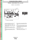
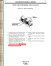
OUTPUT RECTIFIER BRIDGE TEST (continued)
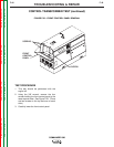
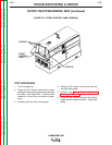
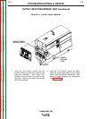
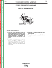
FIGURE F.24 – DIODE LEAD REMOVAL
STATOR AND DIODE
PIGTAIL LEAD
CONNECTIONS
DIODE
HEATSINKS
9. Electrically isolate the six diode pigtail leads
by carefully bending them out into “free air.”
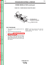
10. With an ohmmeter or diode tester, check
each of the six diodes from their pigtails to
their respective heat sinks.
11. Reverse the tester leads and check the
diodes again. Diodes should have a low
resistance in one polarity and a very high
resistance in the opposite polarity
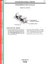
12. Replace any “shorted” or “open” diode as
the tests indicate. See the Diode Removal
and Replacement Procedure.
13. Replace the pigtails and stator leads onto
the correct studs. Assemble the washers
and nuts.
14. Replace the lower front panel and output
leads.
15. Replace the upper control panel and
secure.
16. Replace the front left and right case sides.