


TROUBLESHOOTING & REPAIR
F-53 F-53
COMMANDER 300
Return to Section TOC Return to Section TOC Return to Section TOC Return to Section TOC
Return to Master TOC Return to Master TOC Return to Master TOC Return to Master TOC
OUTPUT RECTIFIER BRIDGE TEST (continued)
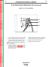
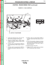
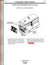
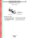
FIGURE F.23 – OUTPUT PANEL REMOVAL
OUTPUT LEADS
(BEHIND PANEL)
GREEN
GROUND
LEAD
SCREWS
7. Using the 3/8" wrench, remove the five
screws holding the lower front panel to the
case front assembly. See Figure F.23.
Carefully move the lower front panel to the
right side. Note that he green ground lead
will still be attached.
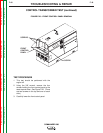
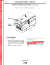
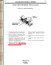
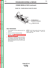
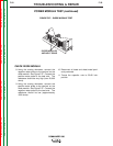
8. Using the 7/16" wrench, remove the stator
leads and diode pigtail leads from the three
studs. Label the leads for reassembly. Note
leads and pigtail placement for reassembly.
See Figure F.24.