


Return to Section TOC Return to Section TOC Return to Section TOC Return to Section TOC
Return to Master TOC Return to Master TOC Return to Master TOC Return to Master TOC
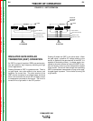
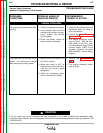
TROUBLESHOOTING & REPAIR
F-5 F-5
COMMANDER 300
TROUBLESHOOTING GUIDE Observe Safety Guidelines
detailed in the beginning of this manual.
CAUTION
If for any reason you do not understand the test procedures or are unable to perform the test/repairs safely,
contact the Lincoln Electric Service Department for electrical troubleshooting assistance before you proceed. Call
1-800-833-9353.
PROBLEMS
(SYMPTOMS)
POSSIBLE AREAS OF
MISADJUSTMENT(S)
RECOMMENDED
COURSE OF ACTION
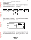
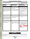
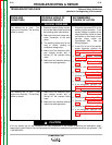
OUTPUT PROBLEMS
No welding output in neither Stick
or CV modes. Also, no auxiliary
power. The engine operates nor-
mally.
1. Check the brushes for wear and
proper contact to the rotor slip
rings.
2. Make sure the engine is operat-
ing at the correct high idle
speed (1900 RPM).
3. Check for loose or faulty con-
nections or leads on the auxil-
iary power studs in the control
box. See the Wiring Diagram.
1. Perform the Rotor Resistance
Test.
2. Perform the Flashing and
Rotor Voltage Test. If the
“flashing” voltage is not present,
the protection board or leads
#201 or #200 may be faulty.
See the Wiring Diagram. Also,
make sure that lead #5P has
continuity (zero ohms) to
ground.
3. Check the field diode and
capacitor. Replace if necessary.
4. Perform the Stator Voltage
Test.
No auxiliary power at the recepta-
cles. The welding output is normal
and the engine operates normally.
1. The circuit breakers may be
tripped. Reset if necessary.
2. Check for loose or faulty con-
nections at the auxiliary recep-
tacles.
1. Check the wiring between the
auxiliary receptacles, the con-
nection studs in the control box,
and the main stator. See the
Wiring Diagram.
2. Perform the Stator Voltage
Test.