


TROUBLESHOOTING & REPAIR
F-98 F-98
COMMANDER 300
Return to Section TOC Return to Section TOC Return to Section TOC Return to Section TOC
Return to Master TOC Return to Master TOC Return to Master TOC Return to Master TOC
STATOR/ROTOR REMOVAL AND REPLACEMENT (continued)
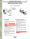
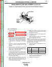
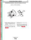
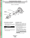
FIGURE F.46 – BRUSH LEAD REMOVAL
12. Label and remove brush leads #201(-) and
#200A(+) and #200B(+) from the brush hold-
er assembly. (The piggy-backed leads con-
nect closest to the stator laminations.) See
Figure F.46.
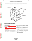
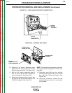
13. Pull the harness containing plug J30, the
brush leads, and the field bridge rectifier
through the bushing in the firewall. See
Figure F.45.
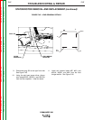
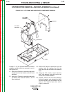
14. Using the 3/8" wrench, remove the brush
holder assembly.
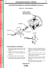
15. Using the 1/2" wrench, disconnect leads
#68A and #69A at their bolted connections
beneath the power module assembly. Label
the leads for reassembly. Cut any neces-
sary cable ties. See Figure F.47.
#200A
#200B
#201