


TROUBLESHOOTING & REPAIR
F-69 F-69
COMMANDER 300
Return to Section TOC Return to Section TOC Return to Section TOC Return to Section TOC
Return to Master TOC Return to Master TOC Return to Master TOC Return to Master TOC
FEEDBACK INPUT TEST (continued)
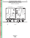
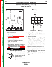
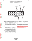
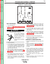
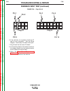
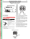
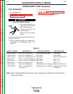
FIGURE F.33. – Plug J2 & J3
Plug J2
Pin 5
Pin 2
Pin 1
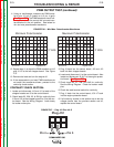
6. If the continuity is not present, check the 67
lead for poor connection. See the Wiring
Diagram. Look closely for broken molex pins.
7. Plug J3 back into the control PC board.
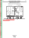
8. If all continuity checks in this section are ok but
the voltage checks from the previous section
are off, replace the control board.
9. Using the Case Cover Removal and
Replacement Procedure, install the control
panel and side panels on the machine.
Pin 6
Plug J3
Pin 15
Pin 2