


TROUBLESHOOTING & REPAIR
F-78 F-78
COMMANDER 300
Return to Section TOC Return to Section TOC Return to Section TOC Return to Section TOC
Return to Master TOC Return to Master TOC Return to Master TOC Return to Master TOC
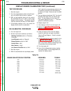
DISPLAY BOARD CALIBRATION TEST (continued)
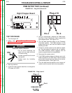
TEST PROCEDURE
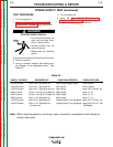
1. Start the engine.
2. Turn the range selector switch to the CC posi-
tion, and control dial to the min. position.
3. With no load applied, slowly turn the control
dial clockwise from min to max in each range
selector switch position. The display should
read the same as the Table F.5 shown below.
4. If the display reading is off in any mode, the
display board must be re-calibrated.
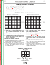
RE-CALIBRATION PROCEDURE
5. Turn the engine off.
6. Set the control panel switches as follows:
Welding Terminals switch to “Remotely
Controlled”.
Local/Remote switch to “Remote”.
Range Selector switch to “60A”.
Control Dial to “Min”.
Idler Switch to “High”.
Arc Control Wire/Stick dial to “Min”.
7. Start the engine.
8. Within 5 seconds after the top display reads
“Crd”, switch the range selector switch to the
CV position and back to the 60A position a
minimum of 5 times. Must end up in the 60A
position.
9. The top display should read “001” for about 5
seconds, then read “CAL” for about 5 sec-
onds. The top display will then read “30”.
The bottom display will read “---”. This com-
pletes the calibration process.
10. Repeat steps 2 & 3.
11. If the display is still off, turn the engine off.
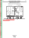
12. Perform the Case Cover Removal and
Replacement Procedure and tilt the control
panel out.
13. Check all leads at J8 & J9 at the display
board for continuity and poor connection.
See the Wiring Diagram. Check for broken
molex pins.
14. If all the leads are ok, perform steps 5 & 6 of
the Control Input Test. Measure the volt-
ages in step 6 at J8 pin 3 (pos. lead) to J9
pin 5 (neg. lead) instead of measuring at the
J2 connector on the control board.
15. Turn the engine off.
16. If any of the voltages were wrong, replace
the control board. If the voltages were ok,
replace the display board.
Table F.5.
RANGE SELECTOR SW. POSITION FROM MIN. TO MAX.
CC
300A
230A
150A
90A
60A
CV
30 amps
140 amps
100 amps
70 amps
50 amps
30 amps
10.5 volts
375 amps
300 amps
230 amps
150 amps
90 amps
60 amps
49-50 volts