


TROUBLESHOOTING & REPAIR
F-76 F-76
COMMANDER 300
Return to Section TOC Return to Section TOC Return to Section TOC Return to Section TOC
Return to Master TOC Return to Master TOC Return to Master TOC Return to Master TOC
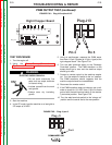
POWER SUPPLY TEST (continued)
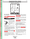
TEST PROCEDURE
1. Turn the engine off.
2. Perform the Case Cover Removal and
Replacement Procedure and tilt the control
panel out.
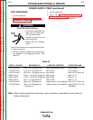
ELECTRIC SHOCK CAN KILL.
• Do not touch electrically live
parts such as output termi-
nals or internal wiring.
• Insulate yourself from the
work and ground.
• Always wear dry insulating
gloves.
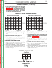
3. Start the machine.
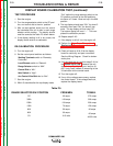
4. Using a voltmeter, measure the following sup-
ply voltages at the designated points. See
Table F.4.
5. Turn the engine off.
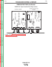
6. Using the Case Cover Removal and
Replacement Procedure, install the control
panel and side panels on the machine.
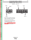
Table F.4
+12VDC control
+12VDC control
+12VDC control
30VAC control
30VAC control
42VAC control
+12VDC control
+12VDC Battery
J2 pin 3 to 2 @ control bd
J1 pin 4 to 1 @ control bd
J5 pin 4 to 1 @ engine prot. bd
J12 pin 1 to 2 @ LT chopper bd
J13 pin 1 to 2 @ RT chopper bd
J3 pin 1 to 9 @ control bd
J9 pin 4 to 5 @ display bd
J9 pin 1 to 2 @ display bd
(run/stop on)
Weld output/display output
Idler control
Idler control
Weld output
Weld output
Weld output
Display output (if so equipped)
Display output (if so equipped)
Control board
Control board
leads 108, 109/cont. bd
leads 15, 16
leads 13, 14
leads 17, 18
leads 106, 107/cont. bd
leads 232, 232J, 5L, 5N,
5M/Battery
SUPPLY VOLTAGE MEASURED AT: FUNCTION AFFECTED CHECK/REPLACE
Note: When checking leads for continuity or poor connection, remember to look closely for
broken molex pins.
WARNING