


INSTALLATION
F-25 F-25
COMMANDER 300
Return to Section TOC Return to Section TOC Return to Section TOC Return to Section TOC
Return to Master TOC Return to Master TOC Return to Master TOC Return to Master TOC
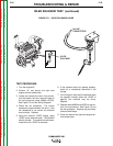
SHUTDOWN SOLENOID TEST (continued)
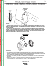
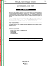
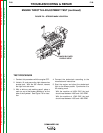
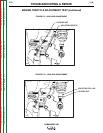
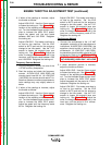
8
7
654
32
1
910
11 12 13 14
15 16
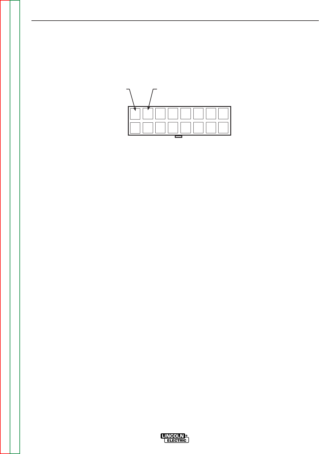
#224(+) #262(-)
J30
5. Check the shutdown solenoid coil resistance
from lead #224 (8J30) to lead #262 (7J30).
The normal resistance is approximately 3
ohms. If the resistance is not correct, the
coil or the diode that is in parallel with the
coil may be faulty. See the Wiring Diagram.
See Figure F.7.
6. Using the external 12VDC supply apply
12VDC to leads #224(+) and #262(-). See
Figure F.7. CORRECT POLARITY MUST
BE OBSERVED OR DAMAGE TO THE
INTERNAL DIODE MAY RESULT. See the
Wiring Diagram. The shutdown solenoid
should activate when the 12VDC is applied.
This can be detected by a “clicking” sound.
7. The solenoid should deactivate when the
12VDC is removed.
8. If the solenoid does not activate when the
12VDC is applied the solenoid or internal
diode may be faulty. Replace.
9. Reconnect plug J30 and P30. Replace any
cable ties previously removed.
10. Reassemble the right front case side and
close the engine service access door.
FIGURE F.7 – PLUG J30 PIN/LEAD ASSIGNMENTS