


Return to Section TOC Return to Section TOC Return to Section TOC Return to Section TOC
Return to Master TOC Return to Master TOC Return to Master TOC Return to Master TOC
GENERAL DESCRIPTION
The Commander 300 is a diesel engine-driven welding
power source capable of producing 300 amps at
32VDC at a 100% duty cycle. The engine is coupled to
a brush-type alternating current generator. This AC
output is rectified and controlled by Chopper
Technology to produced DC current for multi-purpose
welding applications. The Commander 300 is also
capable of producing 10,000 watts of AC auxiliary
power.
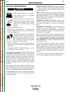
BATTERY, ENGINE, ROTOR, STA-
TOR AND ENGINE PROTECTION
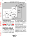
The 12VDC battery powers the engine starter motor
and also supplies power to the engine alternator and
engine protection board. When the engine is started
and running, the battery circuit voltage is fed through
the protection board to the rotor field coil via a brush
and slip ring configuration. This excitation or “flashing”
voltage magnetizes the rotor lamination. The rotor is
mechanically coupled to the engine. This rotating mag-
net induces a voltage in the stationary windings of the
main alternator stator. The stator houses a three-
phase weld winding and also a 115/230VAC single-
phase auxiliary winding. The 115VAC portion of the
auxiliary winding is also rectified and serves as a feed-
back supply for the rotor field winding.
The engine alternator supplies charging current for the
battery circuit. The engine protection board monitors
the sensors and will shut the engine off in the event of
low oil pressure, engine over temperature, malfunction
in the engines alternator system or a low fuel condition.
The idler solenoid is mechanically connected to the
engines throttle linkage. If no welding or auxiliary cur-
rent is being drawn from the Commander 300, the pro-
tection board activates the idler solenoid, which then
brings the engine to a low idle state. When output cur-
rent is sensed, either weld or auxiliary, the protection
board deactivates the idler solenoid and the engine
returns to high RPM.
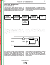
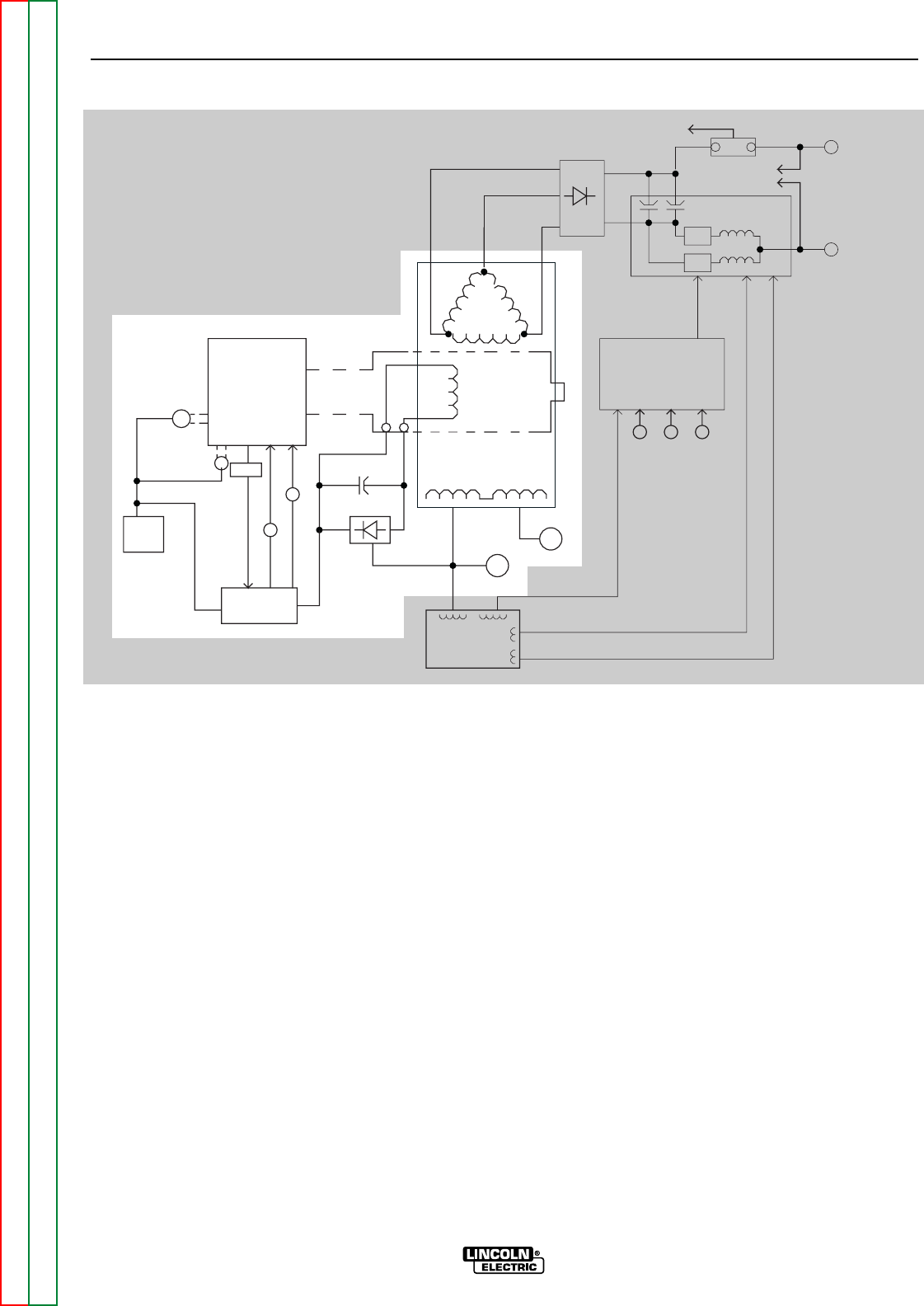
THEORY OF OPERATION
E-2 E-2
COMMANDER 300
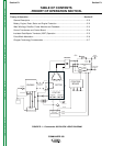
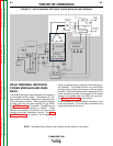
FIGURE E.2 – BATTERY, STARTER, ENGINE, ROTOR, STATOR AND ENGINE PROTECTION
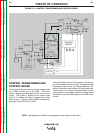
NOTE: Unshaded areas of Block Logic Diagram are the subject of discussion.
ENGINE
CONTROL
BOARD
ROTOR
CONTROL
TRANSFORMER
STATOR
AUXILIARY WINDINGS
ENGINE
PROTECTION
BATTERY
W
E
L
D
W
I
N
D
I
N
G
CHOKE
IGBT
IGBT
SHUNT
TO
CONTROL
BOARD
MECHANICAL
ROTATION
STARTER
ALTERNATOR
ENGINE
SENSORS
SOL
SOL
S
H
U
T
D
O
W
N
I
D
L
E
R
ARC
CONTROL
OUTPUT
CONTROL
MODE
SELECTOR
POWER MODULES
THREE-PHASE
RECTIFIER
WORK
TERMINAL
ELECTRODE
TERMINAL
__
+
42VAC
30VAC
30VAC
1
1
5
V
A
C
115VAC
RECEPTACLE
230VAC
RECEPTACLE
SLIP
RINGS
(TWO)
TO
CONTROL
BOARD