


Return to Section TOC Return to Section TOC Return to Section TOC Return to Section TOC
Return to Master TOC Return to Master TOC Return to Master TOC Return to Master TOC
TROUBLESHOOTING & REPAIR
F-4 F-4
COMMANDER 300
Observe Safety Guidelines TROUBLESHOOTING GUIDE
detailed in the beginning of this manual.
CAUTION
If for any reason you do not understand the test procedures or are unable to perform the test/repairs safely,
contact the Lincoln Electric Service Department for electrical troubleshooting assistance before you proceed. Call
1-800-833-9353.
PROBLEMS
(SYMPTOMS)
POSSIBLE AREAS OF
MISADJUSTMENT(S)
RECOMMENDED
COURSE OF ACTION
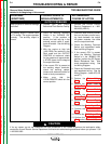
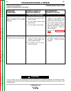
OUTPUT PROBLEMS
Major physical or electrical damage
is evident.
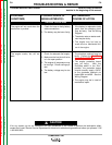
No welding output in neither Stick
or CV modes. The engine operates
normally. The auxiliary output is
normal.
1. Contact your local Lincoln
Authorized Field Service Facility.
1. Place the Welding Terminals
Switch in the “ALWAYS ON”
position. If the problem is
solved, the fault may be in the
external control cable (if used),
leads #2 and #4. See the Wiring
Diagram.
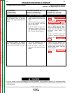
2. With the engine at high idle
(1900 RPM), the machine in the
Stick mode and the OUTPUT
CONTROL at maximum, check
for the presence of approximate-
ly 87VDC (open circuit voltage at
the output terminals.
3. If the correct OCV is present at
the welding output terminals,
check the welding cables,
clamps and electrode holder for
loose or faulty connections.
4. Make sure that the
LOCAL/REMOTE switch is in the
correct position.
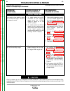
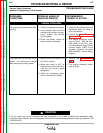
1. Contact the Lincoln Electric
Service Department at 1-800-
833-9353 (WELD).
1. Check for loose or faulty connec-
tions on the heavy current carry-
ing leads between the output,
the power modules, the choke
and the output terminals.
2. Check the Welding Terminals
Switch and associated leads.
See the Wiring Diagram.
3. If the correct OCV is present
when the Welding Terminals
Switch is in the “ALWAYS ON”
position, perform the RF Bypass
Board Resistance Test. Also
check associated wiring. See
the Wiring Diagram.
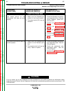
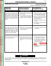
4. Check the Remote/Local switch
and associated wiring. See the
Wiring Diagram. (leads #75, #76
and #77)
5. Perform the Stator Voltage
Test.
6. Perform the Output Rectifier
Bridge Test.
7. Perform the Power Module
Test.
8. Perform the Control Trans-
former Test.
9. Perform the Power Supply
Test.
10. Perform the Control Input Test.
11. Perform the Feedback Input
Test.
12. Perform the PWM Output Test.
13. Perform the Current Balance
Test (codes 10469 & 10470).