


Return to Section TOC Return to Section TOC Return to Section TOC Return to Section TOC
Return to Master TOC Return to Master TOC Return to Master TOC Return to Master TOC
TROUBLESHOOTING & REPAIR
F-32 F-32
COMMANDER 300
ROTOR RESISTANCE TEST (continued)
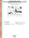
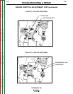
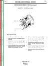
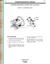
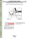
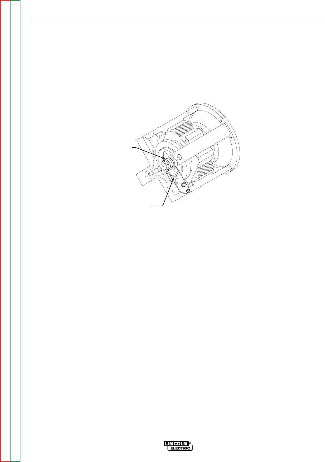
FIGURE F.11 – ROTOR BRUSH LEADS
LEADS REMOVED
SLIP RINGS
TEST PROCEDURE
1 Conduct this test with the engine off.
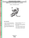
2. Using the 3/8" wrench, remove the left front
case side.
3. Locate, label and remove the three leads
from the rotor brush holder assembly. See
Figure 11. This will electrically isolate the
rotor windings.
4. Using the ohmmeter, check the rotor winding
resistance across the slip rings. Normal
resistance is approximately 23.5 ohms.
5. Measure the resistance to ground. Place
one meter probe on either of the slip rings.
Place the other probe on any good unpaint-
ed ground. The resistance should be very
high, at least 500,000 ohms.
6. If the test does not meet the resistance spec-
ifications, then the rotor may be faulty.
Replace.
7. Connect the leads previously removed from
the brush assembly. Make sure the leads
are connected to the proper brushes.
8. Replace the left front case cover previously
removed.