


Return to Section TOC Return to Section TOC Return to Section TOC Return to Section TOC
Return to Master TOC Return to Master TOC Return to Master TOC Return to Master TOC
TROUBLESHOOTING & REPAIR
F-34 F-34
COMMANDER 300
FLASHING AND ROTOR VOLTAGE TEST (continued)
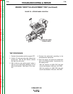
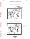
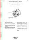
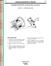
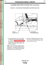
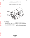
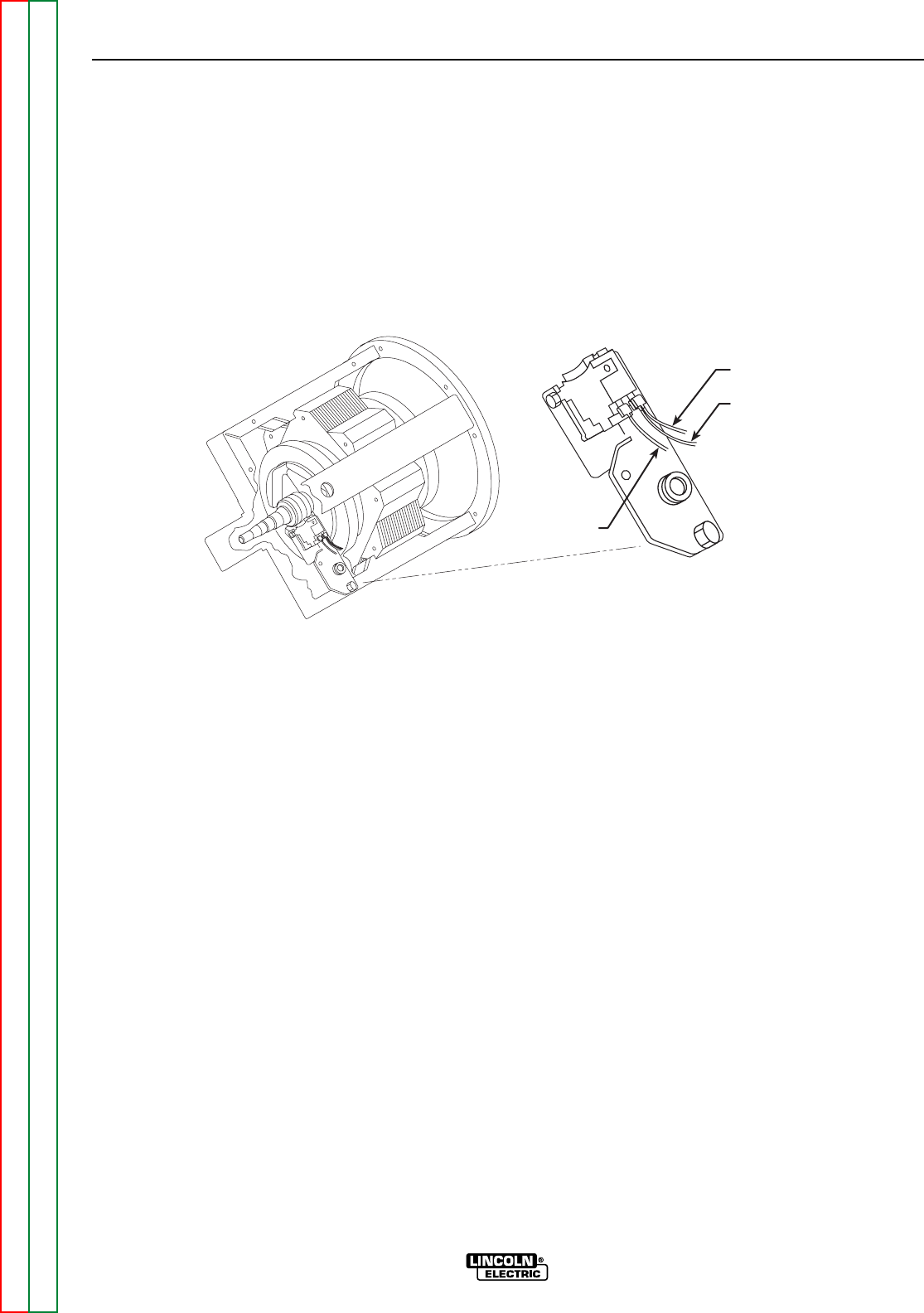
FIGURE F.12 – ROTOR BRUSH LEADS
#200A
#200B
#201
TEST PROCEDURE
1. Using the 3/8" wrench, remove the sheet
metal screws from the left front case side.
2. Carefully remove the left case side.
3. Set the volt/ohmmeter to the DC volts posi-
tion.
4. Connect the positive meter probe to the
brush nearest the rotor lamination (leads
#200A and #200B). See Figure F.12.for
location.
5. Connect the negative meter probe to the
other brush (lead #201).
6. Start the engine and run it at high idle
speed (1900 RPM). Check the voltage
reading on the meter. It should read
approximately 160VDC.