


TROUBLESHOOTING & REPAIR
F-64 F-64
COMMANDER 300
Return to Section TOC Return to Section TOC Return to Section TOC Return to Section TOC
Return to Master TOC Return to Master TOC Return to Master TOC Return to Master TOC
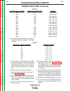
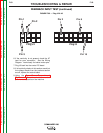
CONTROL INPUT TEST (continued)
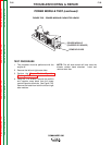
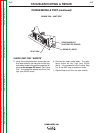
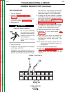
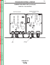
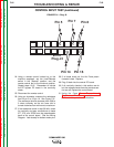
FIGURE F.30 – PLUG J2
G3002-1
COMMANDER 300
CONTROL
Q1
C1
C54
C2
C25
X4
X8
X2
X10 X12 X13
X18
X11
X5 X19
X1
J1
J2
J3
J4
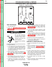
TEST PROCEDURE
1. Turn the engine off.
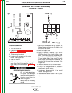
2. Perform the Case Cover Removal and
Replacement Procedure.
3. Tilt the control panel out.
4. Locate the J2 connector on the control
board. See Figure F.30.
5. Start the machine.
6. With a voltmeter, measure the following volt-
ages from J2 pin 6 (pos. lead) to J2 pin 2
(neg. lead) at the control board. See Table
F.2.
ELECTRIC SHOCK CAN KILL.
• Do not touch electrically
live parts such as output
terminals or internal wiring.
• Insulate yourself from the
work and ground.
• Always wear dry insulating
gloves.
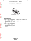
7. Set the Arc Force dial in the min. position, the
Range Selector switch to the CC position, and
the Control dial to min.
8. Short the output studs.
9. Using a voltmeter, measure 4.378 - 4.648
VDC from J2 pin 7 (pos. lead) to J2 pin 2 (neg.
lead). Set the Arc Force dial in the max. posi-
tion. Measure 8.352 - 8.868 VDC from J2 pin
7 (pos. lead) to J2 pin 2 (neg. lead). The short
circuit output current should increase as the
Arc Force dial is turned from min to max. See
Figure F.30.
10. Remove the short and turn the engine off.
11. If any of the voltage checks fail, proceed to
the continuity check section.
12. Locate and disconnect J4 at the control
board. See Figure F.30.
13. Set the range selector switch in the CV posi-
tion.
Plug J2
Pin 6 (+)
Pin 2 (-)
Pin 7 (+)
WARNING