


Return to Master TOC Return to Master TOC Return to Master TOC Return to Master TOC
Section F-1 Section F-1
COMMANDER 300
Troubleshooting & Repair Section ................................................................................Section F
How to Use Troubleshooting Guide.......................................................................................F-2
PC Board Troubleshooting Procedures .................................................................................F-3
Troubleshooting Guide................................................................................................F-4 - F-12
Test Procedures...................................................................................................................F-13
Case Cover Removal and Replacement Procedure ....................................................F-13
Case Front Knobs - Removal and Replacement Procedure.........................................F-18
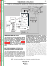
Power Module Capacitor Discharge Procedure ...........................................................F-19
Idler Solenoid Test ........................................................................................................F-21
Shutdown Solenoid Test ...............................................................................................F-23
Engine Throttle Adjustment Test ...................................................................................F-27
Rotor Resistance Test ..................................................................................................F-31
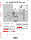
Flashing and Rotor Voltage Test ..................................................................................F-33
Stator Voltage Test .......................................................................................................F-37
RF By-Pass Board Resistance Test .............................................................................F-43
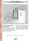
Control Transformer Test ..............................................................................................F-47
Output Rectifier Bridge Test .........................................................................................F-51
Power Module Test........................................................................................................F-55
Current Balance Test.....................................................................................................F-59
Control Input Test ..........................................................................................................F-63
Feedback Input Test ......................................................................................................F-67
PWM Output Test ..........................................................................................................F-71
Power Supply Test.........................................................................................................F-75
Display Board Calibration Test ......................................................................................F-77
Oscilloscope Waveforms......................................................................................................F-79
Normal Open Circuit Voltage Waveform (115 VAC Supply)..........................................F-79
Normal Open Circuit Voltage Waveform (Stick) ............................................................F-80
Normal Weld Voltage Waveform (Stick CC)..................................................................F-81
Normal Weld Voltage Waveform (Wire CV) ..................................................................F-82
Normal Open Circuit Voltage Waveform (Wire CV Tap)................................................F-83
Replacement Procedures ....................................................................................................F-85
Power Module/Output Rectifier Bridge Assembly Removal
and Replacement .......................................................................................................F-85
Power Module (Chopper) PC Board Removal and Replacement ................................F-91
Diode Removal and Replacement ...............................................................................F-93
Stator/Rotor Removal and Replacement .....................................................................F-95
Retest After Repair.............................................................................................................F-104
TABLE OF CONTENTS
TROUBLESHOOTING & REPAIR SECTION