


TROUBLESHOOTING & REPAIR
F-73 F-73
COMMANDER 300
Return to Section TOC Return to Section TOC Return to Section TOC Return to Section TOC
Return to Master TOC Return to Master TOC Return to Master TOC Return to Master TOC
PWM OUTPUT TEST (continued)
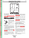
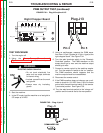
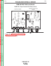
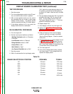
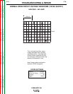
FIGURE F.36 – Min./Max. Potentiometer Waveforms
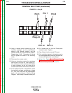
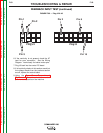
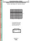
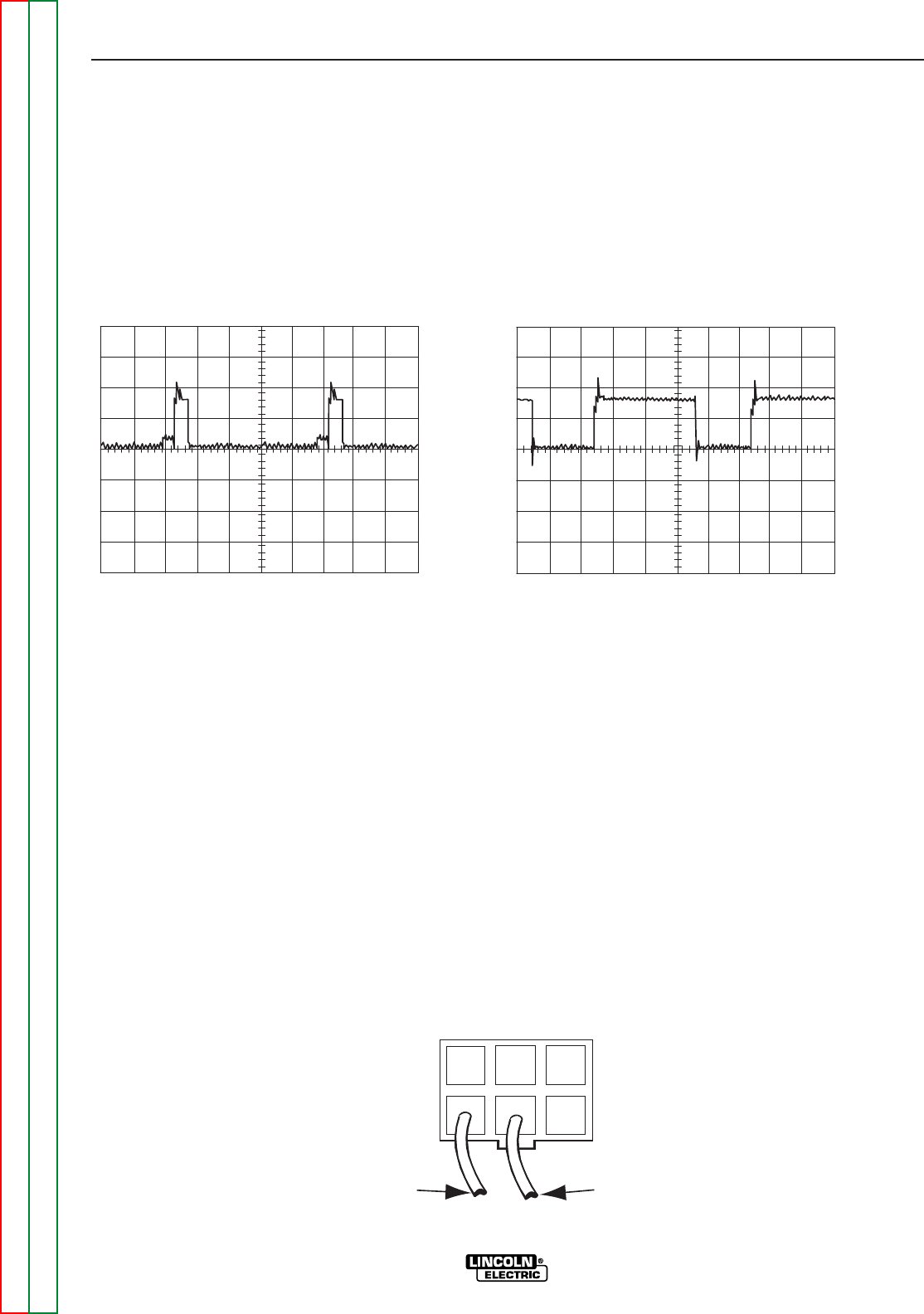
FIGURE F.37 – Plug J12 Pins 4 & 5
Minimum Potentiometer
5V/Div 10µS/Div
0 Volts
Maximum Potentiometer
5V/Div 10µS/Div
0 Volts
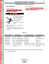
12. Repeat step 11 to check the PWM waveform at J12
pins 4 & 5 at the left chopper board. See Figure
F.37.
13. Remove the load and turn the engine off.
14. If the measured min and max PWM waveforms do
not match the waveforms shown, proceed to the
continuity check section.
CONTINUITY CHECK SECTION:
1. Locate and disconnect J12 and J13 at each of the
chopper boards and J3 at the control board.
2. Check leads 23, 23A, 25, & 25A for continuity from
J12 and J13 at the chopper boardS to J3 at the con-
trol board. See the Wiring Diagram. Look closely
for broken molex pins.
3. Plug J3 back into the control board, J12 and J13
back into their chopper boards.
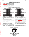
4. Locate and disconnect J1 at the control board. Also
locate and disconnect J5 & J7 at the engine protec-
tion board. See Figure F.38.
5. Check leads 90, 91, 248, and 242 for continuity.
See the Wiring Diagram. Check for broken molex
pins.
6. Check the weld terminal switch for continuity.
7. Plug J1 back into the control board, J5 & J7 back
into the engine protection board.
8. If all continuity checks in this section are ok but the
voltage checks from the previous section are off,
replace the control board.
11. Using an oscilloscope, measure the PWM wave-
form from J13 pin 5 (probe) to J13 pin 4 (gnd).
See Figure F.34. The PWM waveform should uni-
formly decrease as the control dial is turned coun-
terclockwise to the min position. See below for
min and max potentiometer waveforms.
Plug J12
Pin 5
Pin 4