


TROUBLESHOOTING & REPAIR
F-88 F-88
COMMANDER 300
Return to Section TOC Return to Section TOC Return to Section TOC Return to Section TOC
Return to Master TOC Return to Master TOC Return to Master TOC Return to Master TOC
POWER MODULE/OUTPUT RECTIFIER BRIDGE ASSEMBLY
REMOVAL AND REPLACEMENT (continued)
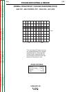
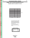
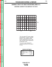
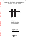
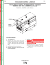
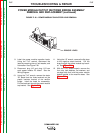
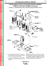
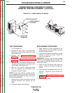
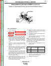
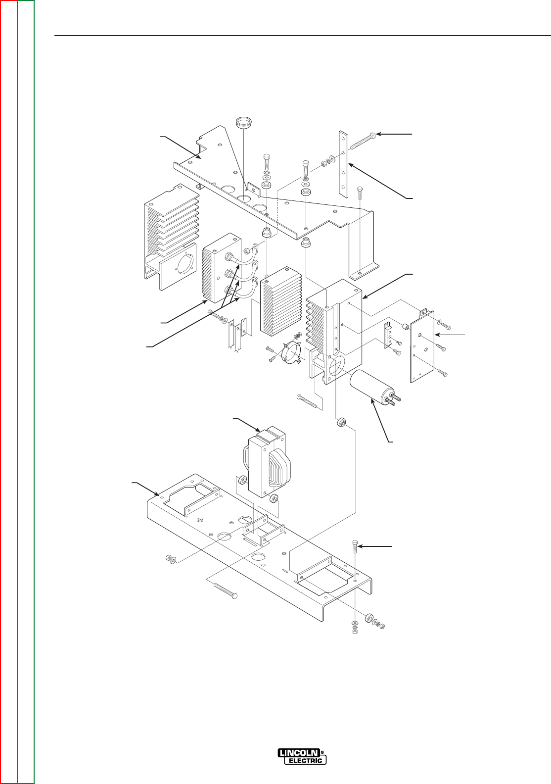
FIGURE F.41 – POWER MODULE/OUTPUT RECTIFIER BRIDGE ASSEMBLY DETAILS
13. Free the positive output lead. Cut any nec-
essary cable ties and slip the lead through
the current sensing toroid assembly.
14. The power module/output rectifier bridge
assembly can now be removed and set to
the side.
NOTE: Leads #68A and #69A will remain
attached between the machine and the assembly.
To completely remove the assembly, label and
disconnect leads #68A and #69A at their bolted
connections beneath the bottom bracket.
DIODE &
"W" LEAD
TERMINAL (3)
GLASTIC
INSULATOR
BRACKET
POWER MODULE
HEAT SINK
POWER
MODULE
PC BOARD
(CHOPPER
PC BOARD)
CAPACITOR
BASE BOLT (4)
CONTROL
TRANSFORMER
DIODE
HEATSINK
DIODE
LEADS
BOTTOM
BRACKET
TOP
BRACKET