


TROUBLESHOOTING & REPAIR
F-68 F-68
COMMANDER 300
Return to Section TOC Return to Section TOC Return to Section TOC Return to Section TOC
Return to Master TOC Return to Master TOC Return to Master TOC Return to Master TOC
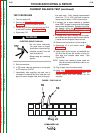
FEEDBACK INPUT TEST (continued)
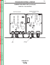
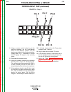
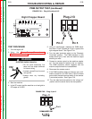
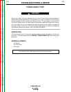
FIGURE F.32 - CONTROL BOARD
G3002-1
COMMANDER 300
CONTROL
Q1
C1
C54
C2
C25
X4
X8
X2
X10 X12 X13
X18
X11
X5 X19
X1
J1
J2
J3
J4
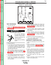
TEST PROCEDURE
1. Turn the engine off.
2. Using the Case Cover Removal and
Replacement Procedure and tilt the control
panel out.
ELECTRIC SHOCK CAN KILL.
• Do not touch electrically
live parts such as output
terminals or internal wiring.
• Insulate yourself from the
work and ground.
• Always wear dry insulating
gloves.
3. Start the machine.
4. In CC mode and with the weld terminal switch
in the “always on” position, load the machine
on a load grid to 200 amps at 25 VDC using
an external ammeter and voltmeter to mea-
sure weld amps and volts.
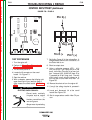
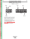
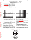
5. With a voltmeter, measure the voltage from J3
pin 15 (pos. lead) to J3 pin 6 (neg. lead). See
Figure F.33. The voltage should be approxi-
mately 25 mvdc.
6. If the voltage is off by more than 2.5 mvdc, the
shunt and lead assembly is bad. Replace.
7. Locate the J2 connector on the control PC
board. Keep the machine running and same
grid load applied.
8. Using a voltmeter, measure the voltage from
J2 pin 1 (pos. lead) to J2 pin 2 (neg. lead).
See Figure F.33. The voltage should read
1.788 - 2.185 VDC.
9. In the CC mode, load the machine to 200
amps at 30 VDC using an external ammeter
and voltmeter.
10. Using a voltmeter, measure the voltage from
J2 pin 5 (pos. lead) to J2 pin 2 (neg.lead).
See Figure F.33. The voltage should read
3.521 - 3.739 VDC.
11. Remove the load and turn the engine off.
12. If any of the voltage checks fail, proceed to
the continuity check section.
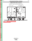
CONTINUITY CHECKS SECTION:
1. Locate and disconnect J3 at the control PC
board.
2. Using an ohmmeter, check for continuity from
J3 pin 15 to J3 pin 6. See Figure F.33. Also
check for continuity from J3 pin 6 to the nega-
tive stud.
3. If either continuity test does not measure 0
ohms, check for continuity and poor connec-
tions on leads 21 and 22 from the shunt back
to the control board. See the wiring diagram.
Look closely for broken molex pins.
4. If all leads check ok, the shunt is bad.
Replace.
5. Using an ohmmeter, check for continuity from
J3 pin 2 to the positive stud.
WARNING