


TROUBLESHOOTING & REPAIR
F-49 F-49
COMMANDER 300
Return to Section TOC Return to Section TOC Return to Section TOC Return to Section TOC
Return to Master TOC Return to Master TOC Return to Master TOC Return to Master TOC
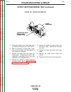
CONTROL TRANSFORMER TEST (continued)
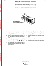
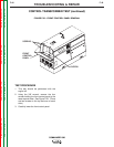
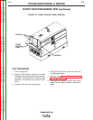
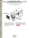
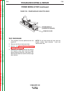
FIGURE F.21 – PLUG J16 DETAILS
J16
4321
56
7
8
J16
CONTROL TRANSFORMER
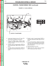
4. Locate and disconnect plug J16 from P16.
See the Wiring Diagram and Figure 21.
5. Using the isolated supply, carefully apply
115VAC to the black (primary) leads at plug
J16 pins 7 and 8.
6. Carefully check for approximately 42VAC at
the red (secondary) leads at plug J16 pins 3
and 4.
7. Carefully check for approximately 30VAC at
the yellow (secondary) leads plug J16 pins 1
and 2.
8. Carefully check for approximately 30VAC at
the brown (secondary) leads plug J16 pins 5
and 6.
9. If any of the secondary voltages are missing
or low the control transformer may be faulty.
Also check the leads at the plug for loose or
faulty connections.
10. Reconnect plugs J16 to P16.
11. Replace the front control panel and secure
with the screws previously removed.