


TROUBLESHOOTING & REPAIR
F-60 F-60
COMMANDER 300
Return to Section TOC Return to Section TOC Return to Section TOC Return to Section TOC
Return to Master TOC Return to Master TOC Return to Master TOC Return to Master TOC
CURRENT BALANCE TEST (continued)
TEST PROCEDURE
1. Turn the engine off.
2. Perform the Case Cover Removal
Procedure and tilt the control panel out.
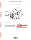
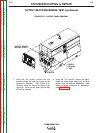
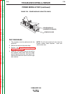
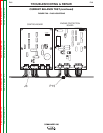
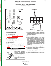
3. Locate plug J3 at the control board and P15
in the main harness. See Figure F.29.
4. Disconnect P15.
ELECTRIC SHOCK CAN KILL.
• Do not touch electrically
live parts such as output
terminals or internal wiring.
• Insulate yourself from the
work and ground.
• Always wear dry insulating
gloves.
5. Start the machine.
6. In CC mode, load the machine on a load grid
to 375 amps at 34 VDC.
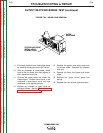
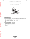
7. Immediately after applying the load, use a
voltmeter to measure (one at a time) the volt-
age from each chopper heat sink to the posi-
tive weld stud. Each voltage measurement
should be .75-1.3 VDC and both measure-
ments must be within .1VDC of each other.
8. A voltage out of spec indicates a possible
blown IGBT chopper module and the chopper
boards must be replaced. Replace both chop-
per boards using the POWER MODULE
(CHOPPER) PC BOARD REMOVAL AND
REPLACEMENT PROCEDURE.
9. A voltage within spec indicates that the chop-
per modules are sharing weld current relative-
ly equal and the chopper boards are ok.
10. Remove the load and turn off the engine.
11. Disconnect J3 at the control board. See
Figure F.29.
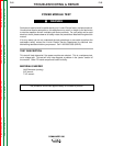
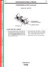
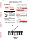
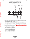
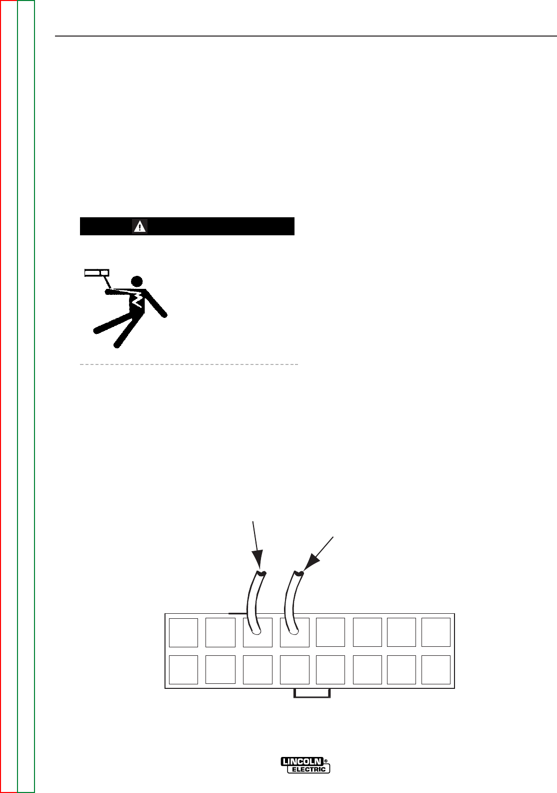
12. Using a pair of wire cutters, cut leads 68 and
69 from the #3 and #4 cavities of plug J3.
Butt tape and insulate loose ends. See
Figure F.28.
NOTE: Cutting and removing these leads will
help to eliminate intermittent lack of out-
put problems.
13. Plug J3 back into the control board.
14. Using the CASE COVER REMOVAL AND
REPLACEMENT PROCEDURE, install the
control panel and side panels on the
machine.
69
68
Plug J3
FIGURE - F.28 PLUG J3
WARNING