


THEORY OF OPERATION
E-4 E-4
COMMANDER 300
Return to Section TOC Return to Section TOC Return to Section TOC Return to Section TOC
Return to Master TOC Return to Master TOC Return to Master TOC Return to Master TOC
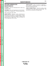
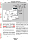
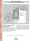
CONTROL TRANSFORMER AND
CONTROL BOARD
The control transformer primary winding is powered by
the 115VAC auxiliary coil in the stator. Three sec-
ondary voltages are developed by the control trans-
former. The 42VAC is applied to the control board
where it is rectified and used to operate the control
board circuitry. The two isolated 30VAC windings sup-
ply power to the IGBT driver circuits.
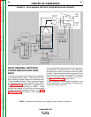
The control board monitors the operator controls (out-
put, mode selector and arc control). It compares these
commands to the current and voltage feedback infor-
mation it receives from the shunt and output terminals.
The circuitry on the control board determines how the
output should be controlled to optimize welding results
and sends the correct PWM signals to the IGBT driver
circuits.
NOTE: Unshaded areas of Block Logic Diagram are the subject of discussion.
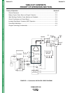
FIGURE E.4 – CONTROL TRANSFORMER AND CONTROL BOARD
ENGINE
CONTROL
BOARD
ROTOR
CONTROL
TRANSFORMER
STATOR
AUXILIARY WINDINGS
ENGINE
PROTECTION
BATTERY
W
E
L
D
W
I
N
D
I
N
G
CHOKE
IGBT
IGBT
SHUNT
TO
CONTROL
BOARD
MECHANICAL
ROTATION
STARTER
ALTERNATOR
ENGINE
SENSORS
SOL
SOL
S
H
U
T
D
O
W
N
I
D
L
E
R
ARC
CONTROL
OUTPUT
CONTROL
MODE
SELECTOR
POWER MODULES
THREE-PHASE
RECTIFIER
WORK
TERMINAL
ELECTRODE
TERMINAL
__
+
42VAC
30VAC
30VAC
1
1
5
V
A
C
115VAC
RECEPTACLE
230VAC
RECEPTACLE
SLIP
RINGS
(TWO)
TO
CONTROL
BOARD