


Return to Section TOC Return to Section TOC Return to Section TOC Return to Section TOC
Return to Master TOC Return to Master TOC Return to Master TOC Return to Master TOC
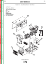
WELD WINDINGS, RECTIFIER,
POWER MODULES AND FEED-
BACK
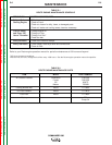
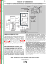
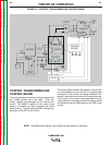
The three-phase stator weld windings are connected to
a three-phase rectifier bridge. The resultant DC volt-
age is applied to parallel capacitors incorporated with-
in the two power modules. These capacitors function
as filters and also as power supplies for the IGBTs.
See IGBT Operation in this section. The IGBTs act as
high-speed switches operating at 20KHZ. These
devices are switched on and off by the control board
through pulse width modulation circuitry. See Pulse
Width Modulation in this section. This “chopped” DC
output is applied through choke coils to the welding out-
put terminals. The chokes function as current filters
and also help to balance the outputs of the two power
modules. Free-wheeling diodes are incorporated in the
power modules to provide a current path for the stored
energy in the chokes when the IGBTs are turned off.
See Chopper Technology in this section.
Output voltage and current feedback information is fed
to the control board. This information is sensed at the
output terminals and the shunt.
THEORY OF OPERATION
E-3 E-3
COMMANDER 300
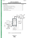
FIGURE E.3 – WELD WINDINGS, RECTIFIER, POWER MODULES AND FEEDBACK
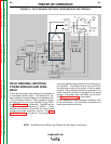
NOTE: Unshaded areas of Block Logic Diagram are the subject of discussion.
ENGINE
CONTROL
BOARD
ROTOR
CONTROL
TRANSFORMER
STATOR
AUXILIARY WINDINGS
ENGINE
PROTECTION
BATTERY
W
E
L
D
W
I
N
D
I
N
G
CHOKE
IGBT
IGBT
SHUNT
TO
CONTROL
BOARD
MECHANICAL
ROTATION
STARTER
ALTERNATOR
ENGINE
SENSORS
SOL
SOL
S
H
U
T
D
O
W
N
I
D
L
E
R
ARC
CONTROL
OUTPUT
CONTROL
MODE
SELECTOR
POWER MODULES
THREE-PHASE
RECTIFIER
WORK
TERMINAL
ELECTRODE
TERMINAL
__
+
42VAC
30VAC
30VAC
1
1
5
V
A
C
115VAC
RECEPTACLE
230VAC
RECEPTACLE
SLIP
RINGS
(TWO)
TO
CONTROL
BOARD