


TROUBLESHOOTING & REPAIR
F-56 F-56
COMMANDER 300
Return to Section TOC Return to Section TOC Return to Section TOC Return to Section TOC
Return to Master TOC Return to Master TOC Return to Master TOC Return to Master TOC
POWER MODULE TEST (continued)
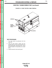
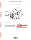
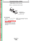
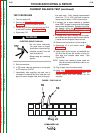
FIGURE F.25 – POWER MODULE CAPACITOR LEADS
REMOVE LEADS
POWER MODULE
(CHOPPER PC BOARD)
TEST PROCEDURE
1. This procedure must be performed with the
engine off.
2. Remove the left and right case sides.
3. Perform the Power Module Capacitor
Discharge Procedure.
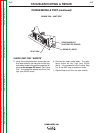
4. Using the 7/16" wrench, remove the positive
and negative strap leads from the power
module capacitor terminals. See Figure F.25.
Remove the leads from both the left and right
side modules.
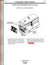
NOTE: The left side module will also have the
bleeder resistor leads attached. Label and
remove them also.