


TROUBLESHOOTING & REPAIR
F-87 F-87
COMMANDER 300
Return to Section TOC Return to Section TOC Return to Section TOC Return to Section TOC
Return to Master TOC Return to Master TOC Return to Master TOC Return to Master TOC
POWER MODULE/OUTPUT RECTIFIER BRIDGE ASSEMBLY
REMOVAL AND REPLACEMENT (continued)
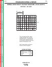
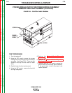
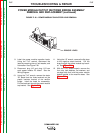
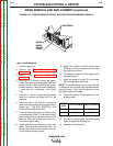
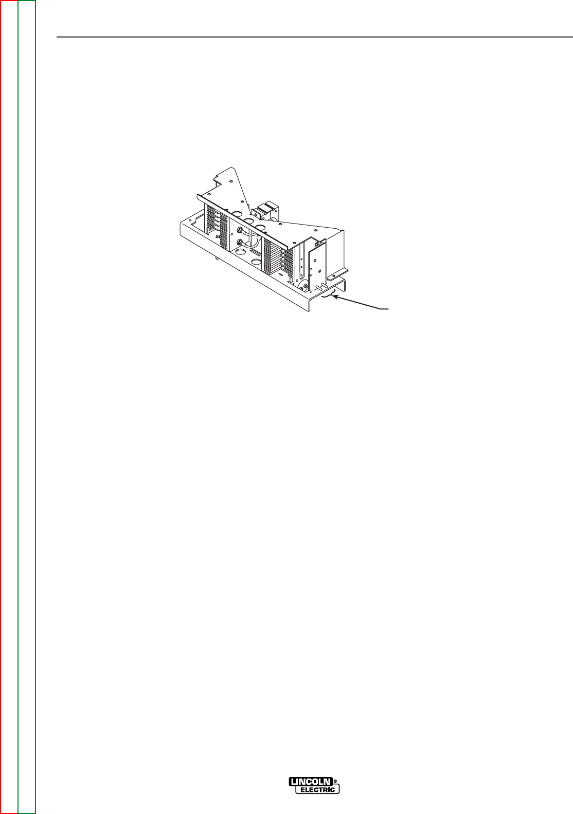
FIGURE F. 40 – POWER MODULE CAPACITOR LEAD REMOVAL
REMOVE LEADS
8. Label the power module capacitor leads.
Using the 7/16" wrench, disconnect the
leads by removing the nut, lock washer, and
flat washer. See Figure F.40.
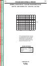
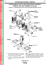
9. Disconnect plug J12 and plug J13 from
each power module PC board. See the
Wiring Diagram.
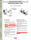
10. Using the 7/16" wrench, remove the stator
“W” leads from the three terminals on the
plastic insulator bracket of the rectifier
bridge. Label the leads for reassembly.
Pull the leads out through the power module
top bracket. See Figure F.41.
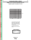
11. Using the 1/2" wrench, remove the flat strap
to the negative output terminal. Pull the
strap through the power module top brack-
et. See Figure F.41.
12. With the 7/16" socket wrench, remove the
four nuts, lock washers, flat washers, and
carriage bolts that hold the power module
bottom bracket to the machine base. See
Figure F.41.