


Return to Section TOC Return to Section TOC Return to Section TOC Return to Section TOC
Return to Master TOC Return to Master TOC Return to Master TOC Return to Master TOC
F-12 F-12
COMMANDER 300
TROUBLESHOOTING & REPAIR
TROUBLESHOOTING GUIDE Observe Safety Guidelines
detailed in the beginning of this manual.
CAUTION
If for any reason you do not understand the test procedures or are unable to perform the test/repairs safely,
contact the Lincoln Electric Service Department for electrical troubleshooting assistance before you proceed. Call
1-800-833-9353.
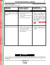
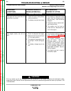
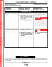
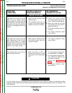
PROBLEMS
(SYMPTOMS)
POSSIBLE AREAS OF
MISADJUSTMENT(S)
RECOMMENDED
COURSE OF ACTION
WELDING PROBLEMS
The welding arc is “cold.” The
engine runs normally. The auxiliary
power is normal.
The welding arc is “hot”. The
engine runs normally. The auxiliary
power is normal.
1. Check for loose or faulty connec-
tions at the weld output terminals
and welding cable connections.
2. Make sure the work clamp has a
clean connection to the work
piece.
3. The welding cables may be too
long or coiled, causing an
excessive voltage drop.
4. Make sure the electrode (wire,
gas, voltage, current, etc.) is
correct for the process being
used.
5. Make sure the machine settings
match the weld application.
1. Make sure the electrode (wire,
gas, voltage, current, ect.) is
correct for the process being
used.
2. Make sure the machine settings
match the weld application.
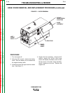
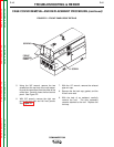
1. Check for the correct OCV at the
welding output terminals. If the
correct voltage is present at the
output terminals, check for loose
connection on the heavy current
carrying leads inside the
Commander 300. See the
Wiring Diagram.
2. If the OCV is low at the welder
output terminals, perform the
Engine Throttle Adjustment
Test.
3. Perform the Output Rectifier
Bridge Test.
4. Perform the Stator Voltage
Test.
5. Perform the Power Module
Test.
6. Perform the Control Input Test.
7. Perform the Feedback Input
Test.
8. Perform the PWM Output Test.
9. If so equipped, perform the
Display Board Calibration
Test.
1. Perform the Power Module
Test.
2. Perform the Control Input Test.
3. Perform the Feedback Input
Test.
4. Perform the PWM Output Test.
5. If so equipped, perform the
Display Board Calibration
Test.