


TROUBLESHOOTING & REPAIR
F-66 F-66
COMMANDER 300
Return to Section TOC Return to Section TOC Return to Section TOC Return to Section TOC
Return to Master TOC Return to Master TOC Return to Master TOC Return to Master TOC
CONTROL INPUT TEST (continued)
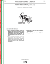
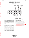
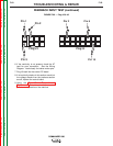
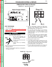
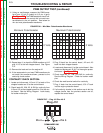
FIGURE F.31 – Plug J3
Pin 7
Plug J3
Pin 8
Pin 16
Pin 14
Pin 5
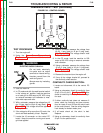
24. Using a remote control hooked up to the
machine amphenol, set the Local/Remote
switch in the “Remote” position, and the
remote control dial to the minimum position.
Repeat steps 19-21. Remember to include
the RF bypass PC board in the continuity
check.
25. Disconnect the remote control.
26. Using an ohmmeter, measure the resistance
from J3 pin 5 to J3 pin 14. See Figure F.31.
The resistance should decrease from 50K to
0 ohms uniformly as the arc force dial is
turned clockwise from minimum to maximum.
27. If the resistance check in step 26 fails, check
for continuity and poor connections on leads
277, 278, and 278A from the potentiometer
back to the control board. See the Wiring
Diagram. Look closely for broken molex pins.
28. If all leads check ok, the Arc Force poten-
tiometer is bad. Replace.
29. Plug J3 back into the control PC board.
30. If all continuity checks in this section are ok
but the voltage checks from the previous sec-
tion are off, replace the control board.
31. Using the Case Cover Removal and
Replacement Procedure, install the control
panel and side panels on the machine.