


TROUBLESHOOTING & REPAIR
F-89 F-89
COMMANDER 300
Return to Section TOC Return to Section TOC Return to Section TOC Return to Section TOC
Return to Master TOC Return to Master TOC Return to Master TOC Return to Master TOC
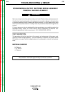
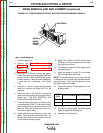
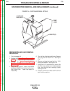
POWER MODULE/OUTPUT RECTIFIER BRIDGE ASSEMBLY
REMOVAL AND REPLACEMENT (continued)
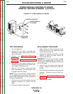
REPLACEMENT PROCEDURE
1. Connect leads #68A and #69A at their bolted
connections beneath the bottom bracket (if
removed).
2. Place the assembly back into the machine.
3. Connect the positive output lead. Feed it
through the toroid assembly.
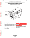
4. Install the four carriage bolts, flat washers,
lock washers, and nuts that hold the bottom
bracket to the machine base.
5. Pull the flat negative output strap through the
top bracket and attach it.
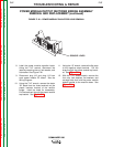
6. Feed the stator “W” leads through the top
bracket and attach them to the terminals on
the plastic insulator bracket.
7. Connect plugs J12 and J13 to the power
module PC board (both sides).
8. Connect the power module capacitor leads.
Torque the capacitor nuts to 50-60 inch-
pounds.
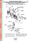
9. Replace any cable ties cut during removal.
10. Install the output panel.
11. Connect the ground wire to the output panel
assembly, if removed.
12. Attach the front left and right side panels
and the front control panel.