


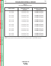
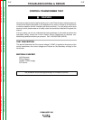
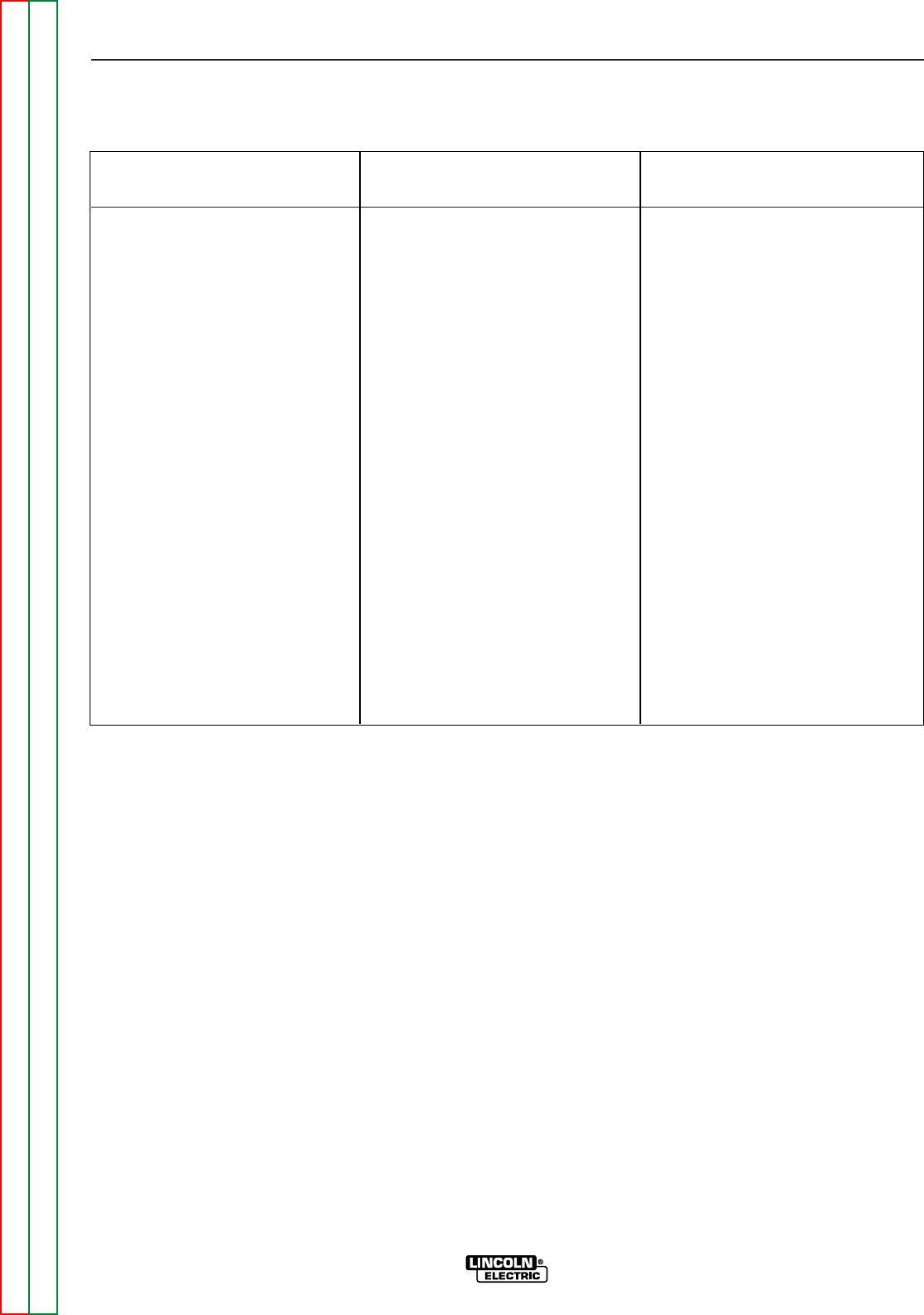
TABLE F.1.
RF BY-PASS RESISTANCE TABLE
CHECK POINTS COMPONENT BEING MAXIMUM ALLOWABLE
CHECKED RESISTANCE
1J61 to 5J60 L4 and Board Trace 4.2 OHMS (3.5 Typical)
1J61 to 5J62 L4 and Board Trace 4.2 OHMS (3.5 Typical)
2J61 to 4J60 L5 and Board Trace 4.2 OHMS (3.5 Typical)
2J61 to 4J62 L5 and Board Trace 4.2 OHMS (3.5 Typical)
3J61 to 1J60 L1 and Board Trace 4.2 OHMS (3.5 Typical)
3J61 to 1J62 L1 and Board Trace 4.2 OHMS (3.5 Typical)
4J61 to 2J60 L2 and Board Trace 4.2 OHMS (3.5 Typical)
4J61 to 2J62 L2 and Board Trace 4.2 OHMS (3.5 Typical)
5J61 to 6J60 L6 and Board Trace 4.2 OHMS (3.5 Typical)
5J61 to 6J62 L6 and Board Trace 4.2 OHMS (3.5 Typical)
8J61 to 3J60 L3 and Board Trace 4.2 OHMS (3.5 Typical)
8J61 to 3J62 L3 and Board Trace 4.2 OHMS (3.5 Typical)
NOTE: The pins should not have continuity to the PC board ground plane. See M18948 schematic.
TROUBLESHOOTING & REPAIR
F-46 F-46
COMMANDER 300
Return to Section TOC Return to Section TOC Return to Section TOC Return to Section TOC
Return to Master TOC Return to Master TOC Return to Master TOC Return to Master TOC