


Return to Section TOC Return to Section TOC Return to Section TOC Return to Section TOC
Return to Master TOC Return to Master TOC Return to Master TOC Return to Master TOC
TROUBLESHOOTING & REPAIR
F-40 F-40
COMMANDER 300
STATOR VOLTAGE TEST (continued)
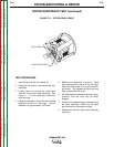
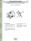
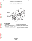
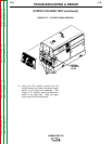
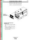
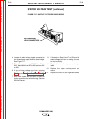
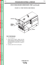
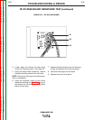
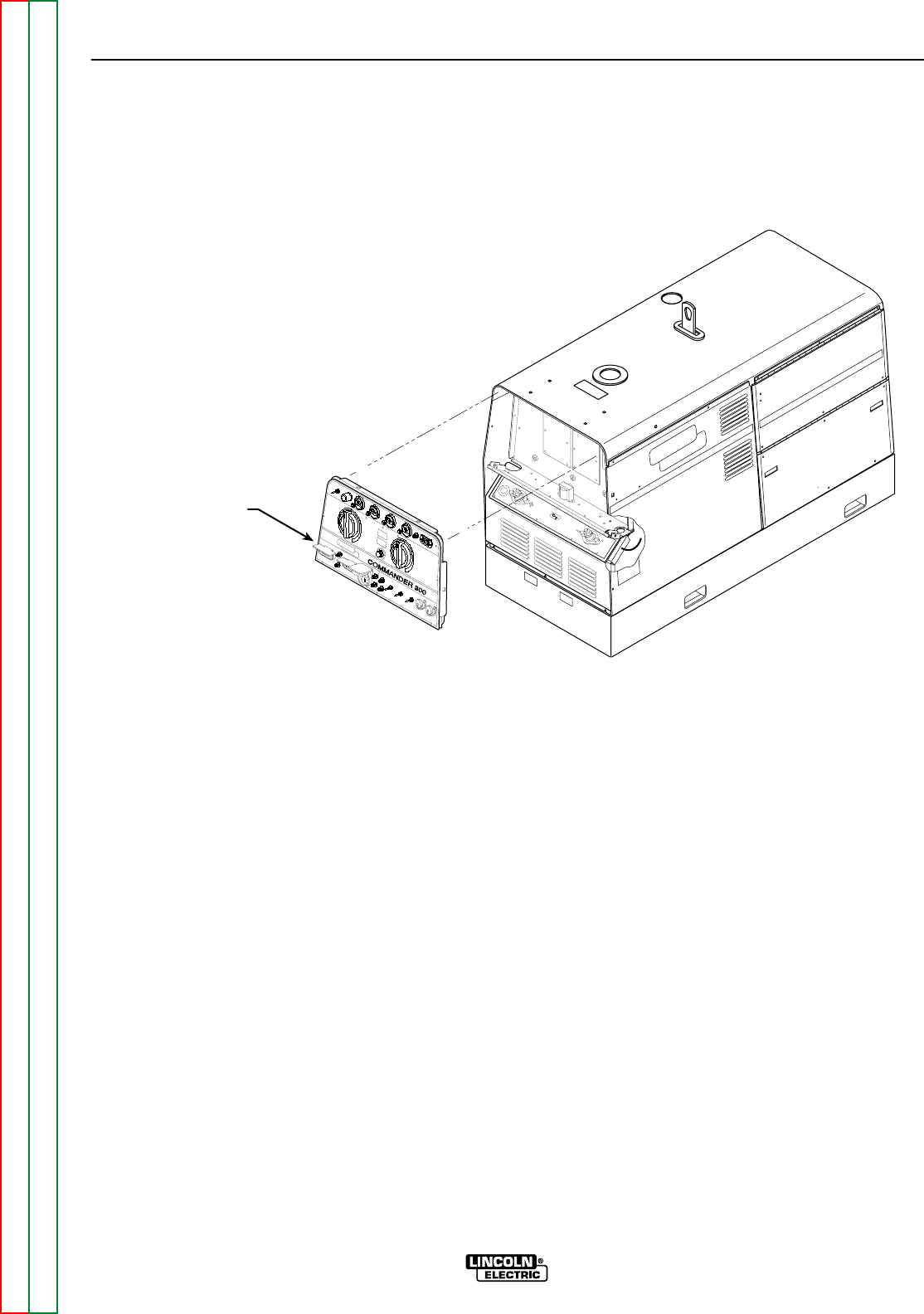
FIGURE F.16 – AUXILIARY LEAD TEST LOCATION
AUXILIARY
LEADS #3, #5, #6
(BEHIND PANEL)
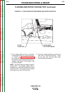
AUXILIARY POWER AND WELD
WINDINGS TEST
1. Start the engine and run at high idle (1900
RPM). Do not load welding or auxiliary
power.
2. Check for 115-132VAC at leads #3 to #5.
Also check for 115-132VAC from leads #6 to
#5. See the Wiring Diagram.
3. Check for 230 to 264VAC at leads #3 to #6.
See the Wiring Diagram.