


TROUBLESHOOTING & REPAIR
F-97 F-97
COMMANDER 300
Return to Section TOC Return to Section TOC Return to Section TOC Return to Section TOC
Return to Master TOC Return to Master TOC Return to Master TOC Return to Master TOC
STATOR/ROTOR REMOVAL AND REPLACEMENT (continued)
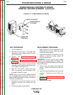
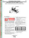
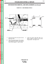
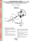
FIGURE F.45 – LEAD REMOVAL DETAILS
FILTER
CAPACITOR
FIELD BRIDGE
RECTIFIER
PLUG J30
9. Disconnect plug J30 at the right front side.
See Figure F.45.
10. Using the slot head screw driver, discon-
nect leads #200C, #200E(+) and #201B(-)
from the filter capacitor. Label the leads.
11. Label and remove leads #5P, #201 and
#201A, #200D, and #6H from the field
bridge rectifier. See Figure F.45.
+
5P
#201
#201A
#64
#200D