


TROUBLESHOOTING & REPAIR
F-103 F-103
COMMANDER 300
Return to Section TOC Return to Section TOC Return to Section TOC Return to Section TOC
Return to Master TOC Return to Master TOC Return to Master TOC Return to Master TOC
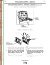
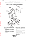
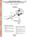
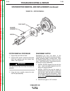
STATOR/ROTOR REMOVAL AND REPLACEMENT (continued)
LEAD RECONNECTION CHECKLIST
Engine
❒ Leads #242D and #229 to fuel level sensor
❒ Plug J30
❒ Brush leads #201(-) and #200A(+) and
#200B(+)
❒ Leads #5P, #201 and #201A, #200D, and
#6H to the field bridge rectifier
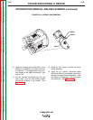
Power Module Supply
❒ Bolted leads #68A and #69A
❒ Stator leads W1-W6
❒ Diode pigtails
Output Panel and Control Box
❒ Lead #5 to ground stud (center)
❒ Lead #5A to auxiliary power ground stud
❒ Lead #6 to auxiliary power stud (left) and
toroid assembly (note number of turns and
direction)
❒ Lead #3 to top 50A circuit breaker
❒ Leads #200C, #200E(+), and #200B(-) to the
field capacitor