


Return to Section TOC Return to Section TOC Return to Section TOC Return to Section TOC
Return to Master TOC Return to Master TOC Return to Master TOC Return to Master TOC
TROUBLESHOOTING & REPAIR
F-35 F-35
COMMANDER 300
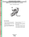
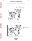
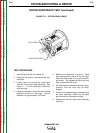
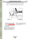
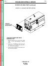
FIGURE F.13 - FIELD DIODE RECTIFIER BRIDGE AND FILTER CAPACITOR
FILTER
CAPACITOR
FIELD DIODE
RECTIFIER BRIDGE
FLASHING AND ROTOR VOLTAGE TEST (continued)
7. If the voltage reading is low or not present,
the generator field is not functioning proper-
ly. Perform the Rotor Resistance Test.
Also check the field diode rectifier bridge, fil-
ter capacitor, and associated leads and con-
nections. See Figure F.13 for location. See
the Wiring Diagram.
NOTE: The normal flashing voltage is approx-
imately 9VDC. This is battery voltage, which is
processed and controlled through the engine
protection board. This voltage must be present
during start-up to “flash” the rotor field.
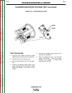
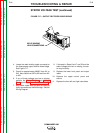
8. If the rotor voltage readings are normal, the
field circuit is functioning properly. Install
the left case side with the sheet metal
screws previously removed.