


TROUBLESHOOTING & REPAIR
F-100 F-100
COMMANDER 300
Return to Section TOC Return to Section TOC Return to Section TOC Return to Section TOC
Return to Master TOC Return to Master TOC Return to Master TOC Return to Master TOC
STATOR/ROTOR REMOVAL AND REPLACEMENT (continued)
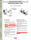
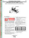
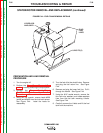
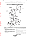
FIGURE F.49 – LIFT FRAME AND ASSOCIATED COMPONENT REMOVAL
LIFT FRAME
WELDMENT
FIREWALL
BASE
FUEL TANK
SUPPORTS
FAN BAFFLE
In steps 21 – 25, the lift frame weldment, fuel tank
supports, and fan baffle are removed as a unit.
See Figure F.49.
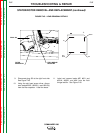
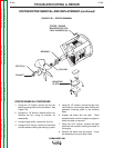
21. Using the 3/8" wrench, remove the two bolts
(at top) that hold the firewall to the lift frame
weldment.
22. Using the 1/2" wrench, remove the two bolts
(at bottom) that hold the firewall to the lift
frame weldment.
23. With the 3/8" wrench, remove the nuts, lock
washers, and flat washers from the two
studs that hold the fan baffle to the machine
base.
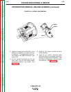
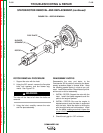
24. Using the 3/4" wrench, remove the four
bolts, lock washers, and nuts from the bot-
tom of the lift frame weldment.
25. Carefully remove the lift frame weldment,
fuel tank supports, and attached fan baffle.
You will need to lift the fan baffle off the two
studs on the machine base, then cock it
slightly to remove it.