


TROUBLESHOOTING & REPAIR
F-58 F-58
COMMANDER 300
Return to Section TOC Return to Section TOC Return to Section TOC Return to Section TOC
Return to Master TOC Return to Master TOC Return to Master TOC Return to Master TOC
POWER MODULE TEST (continued)
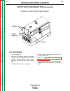
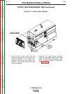
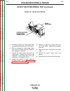
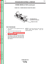
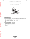
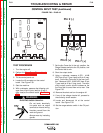
FIGURE F.27 – DIODE MODULE TEST
DIODE MODULES
AND HEAT SINKS
CHECK DIODE MODULE
8. Using the analog ohmmeter, connect the
negative meter probe to the terminal on the
diode module. See Figure F.27. Connect the
positive meter probe to the heat sink. The
resistance should be very high (over 20,000
ohms).
9. Using the analog ohmmeter, connect the
positive meter probe to the terminal on the
diode module. See Figure F.27. Connect the
negative meter probe to the heat sink. The
resistance should be low (approximately
1000 ohms).
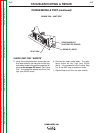
10. Reconnect all leads and sheet metal previ-
ously removed.
11.Torque the capacitor nuts to 50-60 inch-
pounds.