


Return to Section TOC Return to Section TOC Return to Section TOC Return to Section TOC
Return to Master TOC Return to Master TOC Return to Master TOC Return to Master TOC
TROUBLESHOOTING & REPAIR
F-16 F-16
COMMANDER 300
OUTPUT LEADS
(BEHIND PANEL)
GREEN
GROUND
LEAD
SCREWS
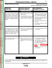
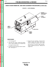
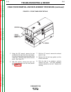
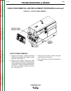
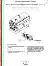
FIGURE F.3 – OUTPUT PANEL REMOVAL
CASE COVER REMOVAL AND REPLACEMENT PROCEDURE (continued)
OUTPUT PANEL REMOVAL
1. Using the 3/4" wrench, remove the internal
leads from the positive and negative output
terminals. See Figure F.3.
2. Using the 3/8" wrench, remove the three
screws along the bottom of the output panel.
Then remove the two screws holding the top
of the panel. These are accessed in the con-
trol box, on the bottom at each side of the
box. See Figure F.3.
3. Using the 3/8" wrench, remove the green
ground lead from the panel.
4. The output panel can now be removed and
set aside.