


TROUBLESHOOTING & REPAIR
F-72 F-72
COMMANDER 300
Return to Section TOC Return to Section TOC Return to Section TOC Return to Section TOC
Return to Master TOC Return to Master TOC Return to Master TOC Return to Master TOC
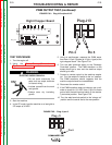
PWM OUTPUT TEST (continued)
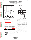
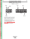
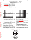
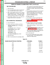
FIGURE F.34 – Plug J13 w/pins 4 & 5
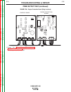
FIGURE F.35 – Plug J1 pin 6
+
Plug J13
J13
Right Chopper Board
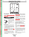
TEST PROCEDURE
1. Turn the engine off.
2. Using the Case Cover Removal and
Replacement Procedure and tilt the control panel
out.
ELECTRIC SHOCK CAN KILL.
• Do not touch electrically live
parts such as output terminals
or internal wiring.
• Insulate yourself from the work
and ground.
• Always wear dry insulating
gloves.
3. Start the machine.
4. In the CC mode, load the machine on a load grid to
375 amps at 34 VDC.
5. Using an oscilloscope, measure the PWM wave-
form from J13 pin 5 (probe) to J13 pin 4 (gnd) at the
right chopper board. See Figure F.34.
6. Turn the weld terminals switch to the “Remotely
Controlled” position. The PWM waveform on the
scope should go to zero and the machine output
should go to zero.
7. Connect a remote control to the machine amphe-
nol. Turn the remote 2-4 switch to the “on” position.
The PWM waveform should reappear and the
machine output should be re-established.
8. Disconnect the remote control.
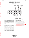
9. If the PWM waveform does not change, use a volt-
meter to check for 10.0 VDC from J1 pin 6 to frame
ground with the weld terminal switch in the remote-
ly controlled position. See Figure F.35.
10. Turn the weld terminals switch to the “always on”
position and the control dial to the max position.
Plug J13
Pin 5
Pin 4
Plug J1
Pin 6
WARNING