


TROUBLESHOOTING & REPAIR
F-52 F-52
COMMANDER 300
Return to Section TOC Return to Section TOC Return to Section TOC Return to Section TOC
Return to Master TOC Return to Master TOC Return to Master TOC Return to Master TOC
OUTPUT RECTIFIER BRIDGE TEST (continued)
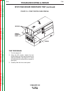
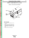
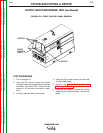
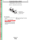
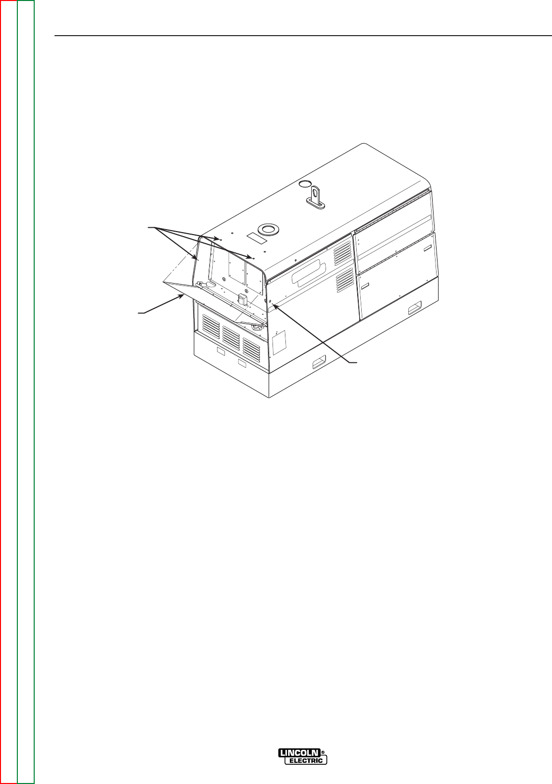
FIGURE F.22 – FRONT CONTROL PANEL REMOVAL
FRONT
CONTROL
PANEL
SCREWS
SCREW
TEST PROCEDURE
1. Turn the engine off.
2. Using the 3/8" wrench remove the screws
holding the front control panel to the case top
and sides. See Figure F.22. (There are two
screws on the top and one screw on each
side.)
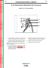
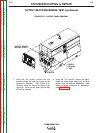
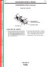
3. Carefully lower the front control panel.
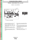
4. Using the 3/8" wrench, remove the front left
and right side panels.
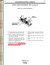
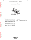
5. Perform the Power Module Capacitor
Discharge Procedure.
6. Using the 3/4" wrench, remove the internal
leads from the output terminals. Insulate the
leads.