


TROUBLESHOOTING & REPAIR
F-99 F-99
COMMANDER 300
Return to Section TOC Return to Section TOC Return to Section TOC Return to Section TOC
Return to Master TOC Return to Master TOC Return to Master TOC Return to Master TOC
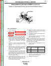
STATOR/ROTOR REMOVAL AND REPLACEMENT (continued)
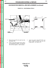
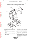
16. Using the 7/16" wrench, disconnect stator
lead #6 from the auxiliary power stud on the
left side of the control box. See Figure F.48.
17. With the 3/8" wrench, disconnect lead #5
from the center ground stud (nearest the
control transformer). See Figure F.48.
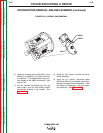
18. Using the phillips screw driver, remove lead
#3 from the top 50A circuit breaker for the
120/240V receptacle. See Figure F.48.
NOTE: This lead must be wound two turns clock-
wise through the toroid (opposite in direction from
lead #6A).
19. Disconnect lead #5A from the auxiliary
power ground stud (left side of the control
box, next to the 120V circuit breaker). See
Figure F.48.
20. Using the 3/8 wrench, remove the two
screws holding the control box to the top of
the fan baffle.
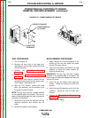
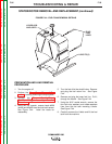
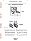
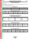
FIGURE F.47 – LEADS #68A/#69A BOLTED CONNECTIONS
POWER
MODULE
ASSEMBLY
BOLTED
CONNECTION-
LEADS 68A / 69A
POWER STUD &
LEADS #5A, #6
GROUND STUD
& LEAD #5
TOP 50A
CIRCUIT BREAKER
(LEAD #3 ON BACK)
FIGURE F.48 – CONTROL BOX LEADS