


TROUBLESHOOTING & REPAIR
F-57 F-57
COMMANDER 300
Return to Section TOC Return to Section TOC Return to Section TOC Return to Section TOC
Return to Master TOC Return to Master TOC Return to Master TOC Return to Master TOC
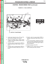
POWER MODULE TEST (continued)
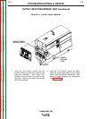
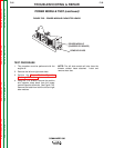
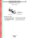
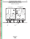
FIGURE F.26 – IGBT TEST
REMOVE LEADS
POWER MODULE
(CHOPPER PC BOARD)
HEAT SINK
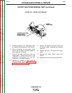
CHECK IGBT FOR “SHORTS”
5. Using the analog ohmmeter, connect the pos-
itive meter probe to the heat sink and the neg-
ative meter probe to the positive capacitor ter-
minal on the chopper PC board. See Figure
F.26. The resistance reading should be very
high (over 20,000 ohms).
6. Reverse the meter probe leads. The resis-
tance should be very high (over 20,000
ohms). It the resistance is low in either Step
5 or 6, the IGBT may be shorted or leaky.
7. Repeat Steps 4 and 5 for the other module.