E6581301
F-20
6
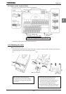
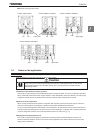
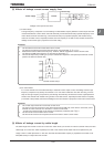
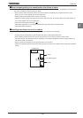
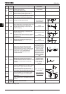
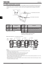
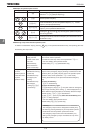
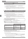
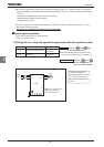
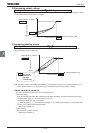
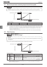
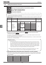
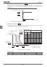
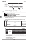
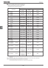
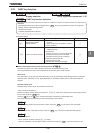
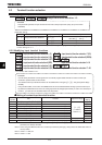
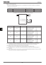
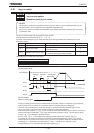
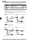
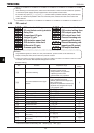
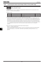
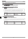
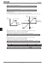
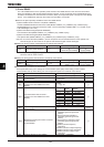
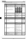
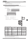
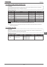
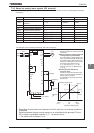
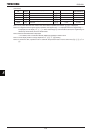
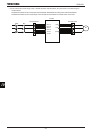
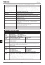
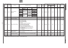
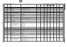
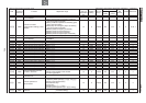
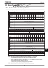
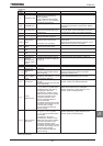
[Setting of jog run setting terminal (S3-CC)]
Assign control terminal S3 ([: preset speed 3] in default setting) as the jog run setting terminal.
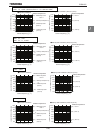
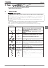
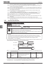
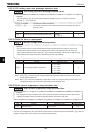
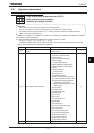
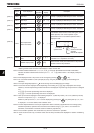
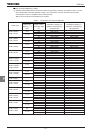
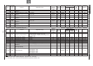
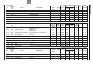
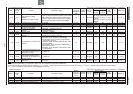
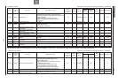
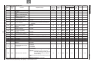
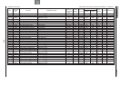
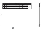
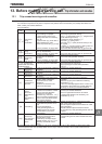
Title Function Adjustment range Example of setting
H Input terminal function selection 7 (S3) ~ (Jog run setting terminal)
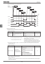
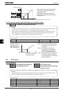
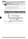
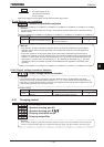
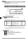
Note: During the jog run mode, there is LOW (low speed detection signal) output but no RCH (designated
frequency reach signal) output, and PID control does not work.
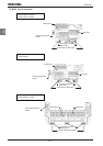
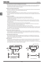
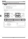
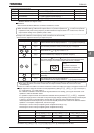
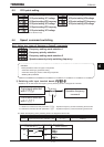
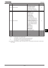
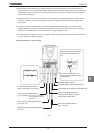
•When the inverter is in panel jog mode, pressing the key displays
HLQI
, while pressing the key displays
TLQI
.
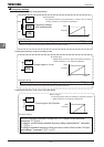
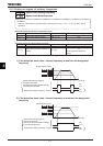
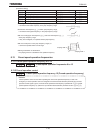
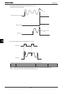
•When HLQI is displayed, the inverter will be placed in forward jog run mode as long as the key is held down.
•When TLQI is displayed, the inverter will be placed in reverse jog run mode as long as the key is held down.
•During jog run, the direction of rotation can be changed using the and keys. Press the key to run
the motor in the forward direction, or press the key to run it in the reverse direction.
•If you press and hold down the key for 20 seconds or more, the key failure alarm “G” will be displayed.
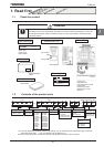
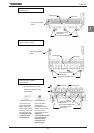
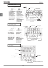
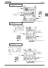
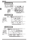
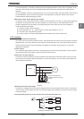
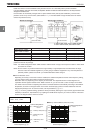
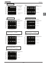
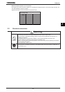
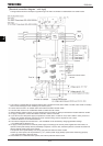
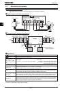
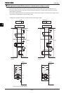
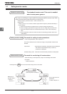
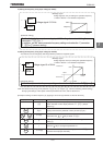
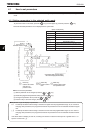
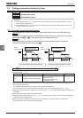
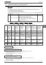
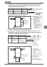
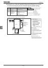
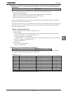
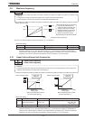
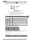
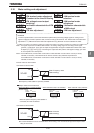
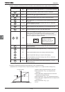
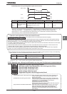
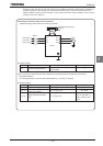
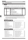
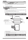
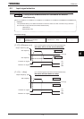
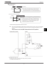
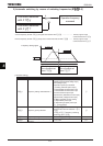
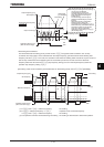
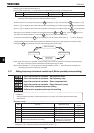
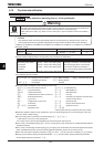
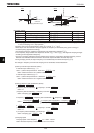
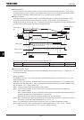
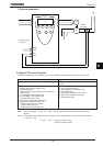
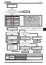
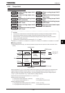
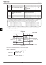
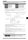
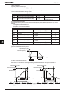
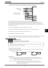
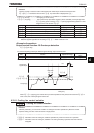
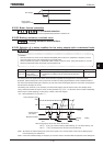
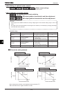
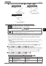
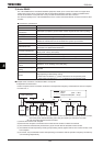
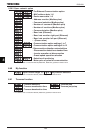
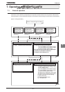
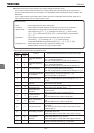
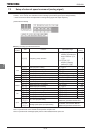
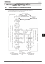
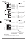
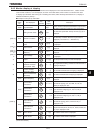
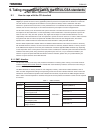
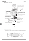
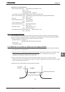
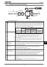
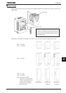
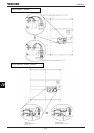
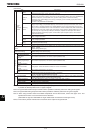
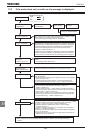
The figure below shows the relationship between the operation panel jog run mode and each of the other modes.
Pressing the key, which will move the inverter through each of the modes.
Status monitor mode
Status monitor mode
Status monitor mode
MODE
Operation panel
jog run mode
Note1: When the inverter is in operation (RUN key lamp is lit) or when an operation command is issued (RUN key
lamp is lit), the inverter cannot be switched to operation panel jog run mode.
Note 2: When parameter H (input terminal priority selection) is set to , the inverter does not display any
message saying that it is in panel jog run mode.
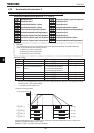
6.11
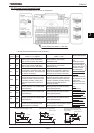
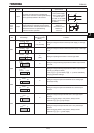
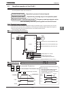
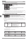
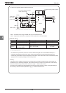
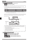
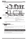
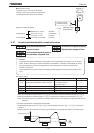
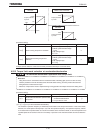
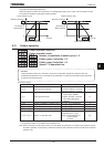
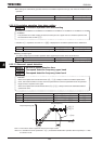
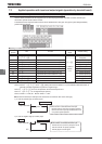
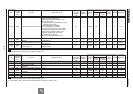
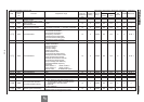
Setting frequency via external contact input (Motor operated pot mop setting)
H
HH
H
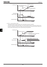
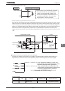
: Input from external contacts - Up response time
H
HH
H
: Input from external contacts - Up frequency step
H
HH
H
: Input from external contacts - Down response time
H
HH
H
: Input from external contacts - Down frequency step
H
HH
H
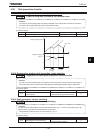
: Initial motor operated pot mop setting
H
HH
H
: Initial motor operated pot mop set rewriting
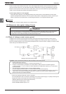
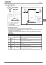
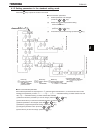
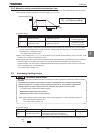
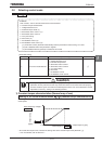
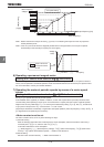
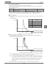
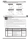
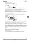
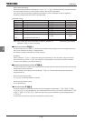
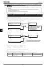
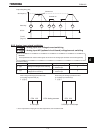
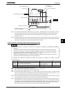
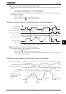
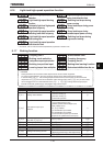
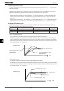
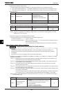
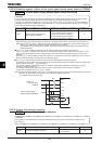
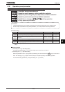
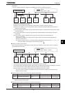
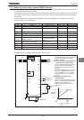
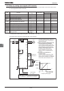
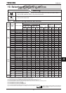
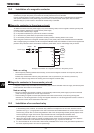
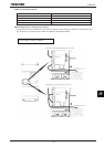
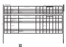
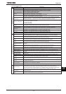
• Function
These parameters are used to set the output frequency by means of a contact signal from the external
control device.
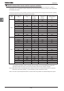
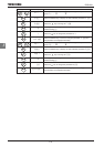
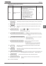
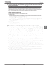
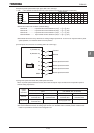
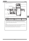
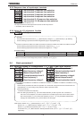
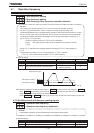
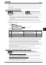
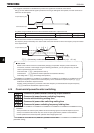
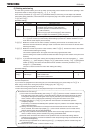
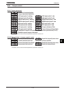
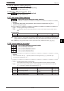
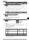
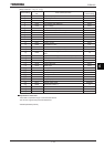
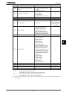
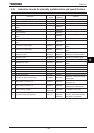
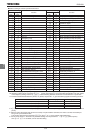
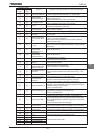
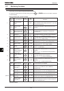
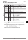
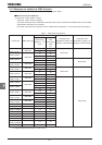
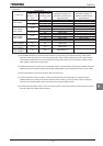
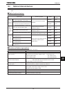
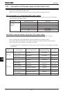
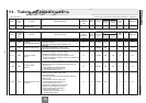
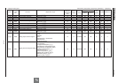
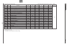
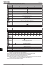
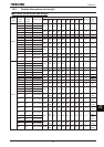
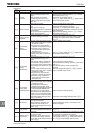
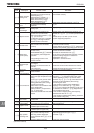
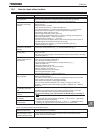
[Parameter setting]
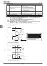
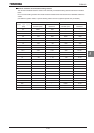
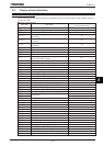
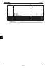
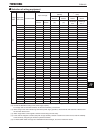
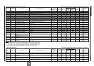
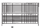
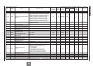
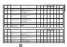
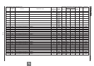
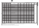
Title Function Adjustment range
Default
setting
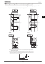
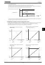
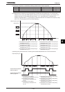
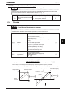
H
Input from external contacts - Up response time ~ s
H
Input from external contacts - Up frequency step ~ HJ Hz
H
Input from external contacts - Down response time ~ s
H
Input from external contacts - Down frequency step ~ HJ Hz
H
Initial motor operated pot mop setting NN~ WNHz
H
Initial motor operated pot mop setting
:Not changed
:Setting of H changed
when power is turned off.
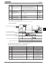
★
These functions are operative when parameter HOQF (frequency setting mode selection 1) is set to or
parameter H (frequency setting mode selection 2) is set to .
RUN
RUN
RUN
MODE