


E6581301
F-84
6
2) 4-wire RS485
The 4-wire RS485 device included as standard equipment, allows you to connect the inverter to a higher-level
system (host) and to set up a network for data communications between inverters. It makes it possible for the
inverter to be linked to a computer and to carry out data communications with other inverters.
The connector (RJ45) for the 4-wire RS485 device on the control circuit terminal block is used to connect to other
inverters.
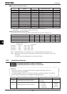
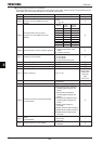
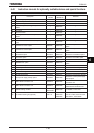
■ Transmission specifications
Item Specifications
Interface Compliant with RS485
Transmission path
specification
Half-duplex type [Buss type (terminator resistor required at each end of system)]
Wiring type Compatible with both 4-wire and 2-wire types
Transmission distance Up to 500m (overall length of the cable)
Number of connectable
units
Up to 32 units (including the host computer)
Number of inverters that can be connected in a system: Up to 32 units
Synchronization scheme Asynchronous
Transmission rate
Default: 19200 baud (parameter setting)
Selectable from 9600/19200/38400 baud
Character transmission
ASCII mode : JIS X 0201 8-bit (ASCII)
Binary code : Binary, 8-bit (fixed)
Stop bit length Inverter receiving: 1 bit, Inverter sending: 2 bits
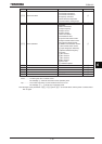
Error detection Parity: Even, Odd, or None selectable by parameter setting; check sum method
Error correction Not provided
Response monitoring Not provided
Character transmission
format
Reception: 11 bit, Sending: 12 bit (with parity)
Transmission waiting time
setting
Possible
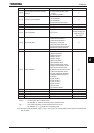
Others
Inverter’s action at the occurrence of a communication timeout selectable from
tripping/raising an alarm/doing nothing
→When alarm is selected, “V” blinks at the left end of the operation panel
When tripping is selected, “GTT” is displayed on the operation panel
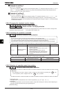
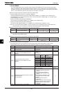
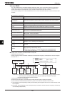
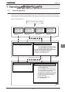
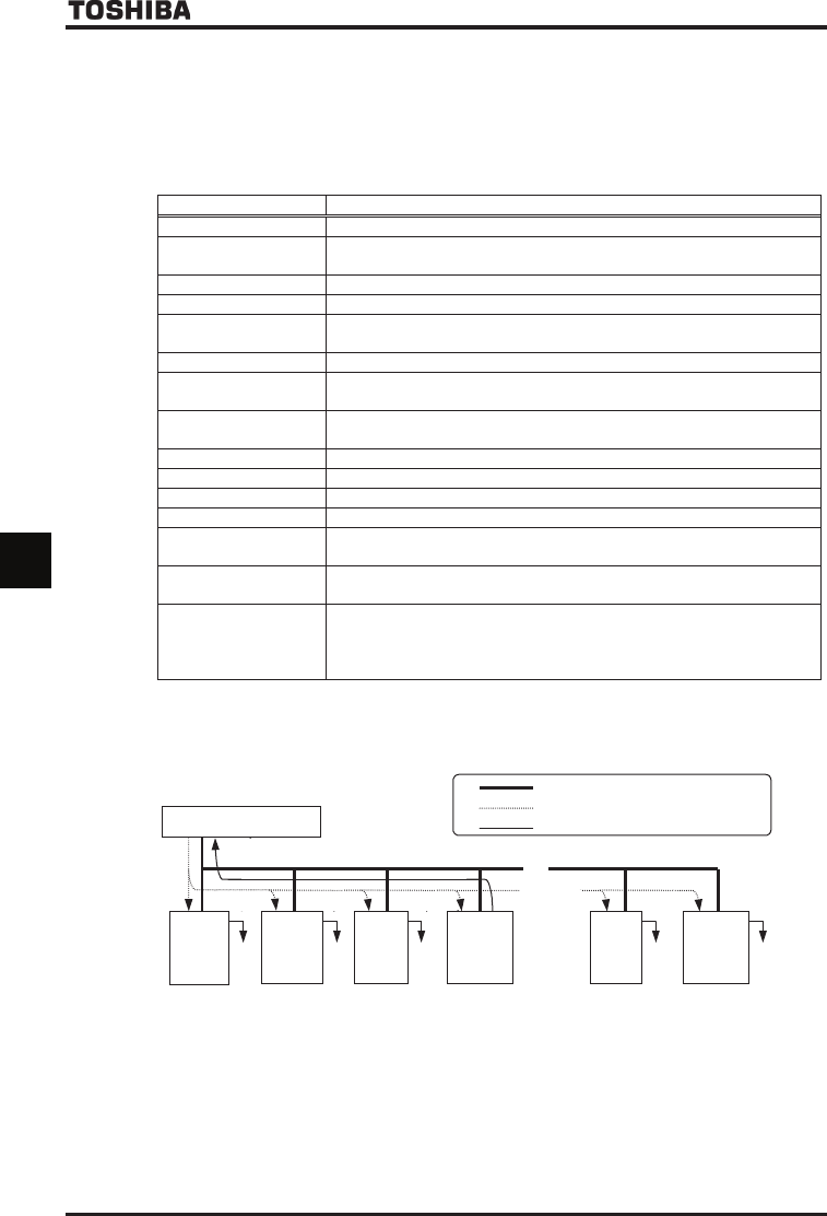
■ Example of the connection of inverters linked to a computer
<Independent communication>
Perform computer-inverter connection as follows to send operation frequency commands from the host computer
to inverter No. 3:
Host computer
INV
No.29
INV
No.30
~
~
: Wiring
: Data (host
→
INV)
: Response data (INV → host)
Given
away
Given
away
Given
away
Given
away
Given
away
INV
No.03
INV
No.02
INV
No.01
INV
No.00
Ŭ
Ŭ
Ŭ
Ŭ
Ŭ
“Given away”: Only the inverter with the selected inverter number conducts data processing. All other inverters,
even if they have received the data, give it away and stand by to receive the next data.
Ŭ: Use the terminal board to branch the cable.
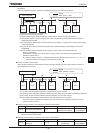
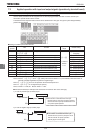
(1) Data is sent from the host computer.
(2) Data from the computer is received at each inverter and the inverter numbers are checked.
(3) The command is decoded and processed only by the inverter with the selected inverter number.
(4) The selected inverter responds by sending the processing results, together with its own inverter number, to the
host computer.
(5) As a result, only the selected inverter starts operating in accordance with the operation frequency command by
communicating independently.