


E6581301
F-59
6
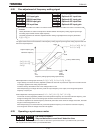
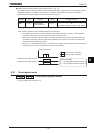
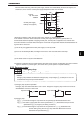
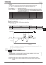
Be sure to select this setting if the main power supply is turned on and off endlessly for reasons of sequence, as
shown below, in the event the control power supply backup device fails or not connected.
R/L1
S/L2
T/L3
+SU
CC
FLA
FLB
FLC
MC
RUN
Control power supply
backup device (option)
In case of
3
φ
- 200~240V
-50/60Hz
MC
RUN
<Example of a situation in which the main power supply is turned on and off endlessly>
In the example of connection shown above, if the control power supply 4backup device (optional) fails or not
connected and becomes incapable of supplying control power, control power is supplied from the inverter’s main
circuit and operation is continued without interruption. If the inverter is tripped under these circumstances because of
a ground fault or overcurrent :
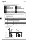
(1) The FL relay is triggered and the main power supply is shut off by the MC.
↓
(2) As a result of shutoff by the MC, the voltage in the inverter’s main circuit and control circuit drop.
↓
(3) As a result of a drop in control voltage, the FL relay recovers from a trip.
↓
(4) The release of the FL relay turns the MC back on.
↓
(5) Operation is restarted and if the problem causing the inverter to be tripped is not eliminated, the inverter is tripped
again, the situation in (1) arises again, and thus the above cycle of operation is repeated endlessly.
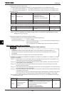
6.33.3 Emergency stop
H
HH
H : Emergency stop
H
HH
H : Emergency DC braking control time
• Function
Emergency stop mode can be selected. At emergency stop, a trip message (“
G
”) is displayed. FL relay can
be deactivated using the output function selection.
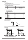
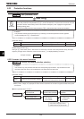
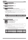
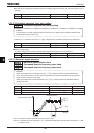
1) Emergency stop by terminal operation
Emergency stop can be performed with the a or b-contact. Assign the emergency stop function to a terminal as
described below, and select a stop mode.
a-contact
CC
Input terminal
b-contact
CC
Input terminal
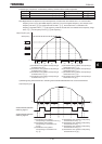
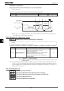
2) Emergency stop
H=: The motor is brought to a stop within the time specified with selected deceleration time.
H=: DC braking is performed at the current specified with H (DC braking current) for the time
specified with H (emergency DC braking control time).
H=: The motor is brought to a stop within the time specified with H (deceleration time 4).
Use this setting to bring the motor to a stop within time different from the normal
deceleration time specified with FGE.