E6581301
G-12
7
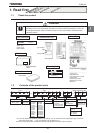
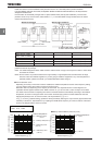
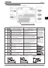
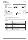
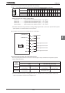
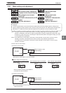
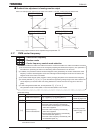
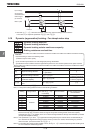
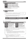
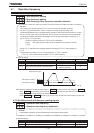
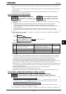
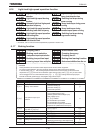
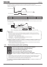
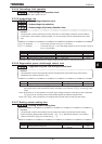
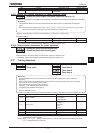
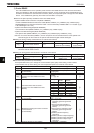
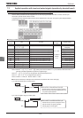
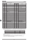
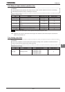
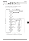
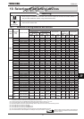
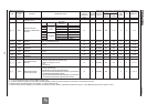
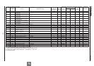
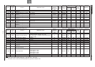
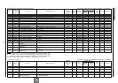
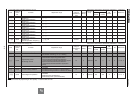
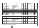
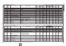
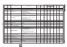
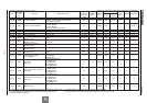
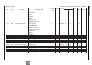
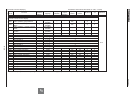
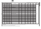
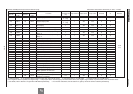
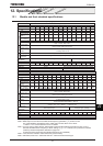
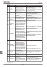
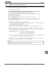
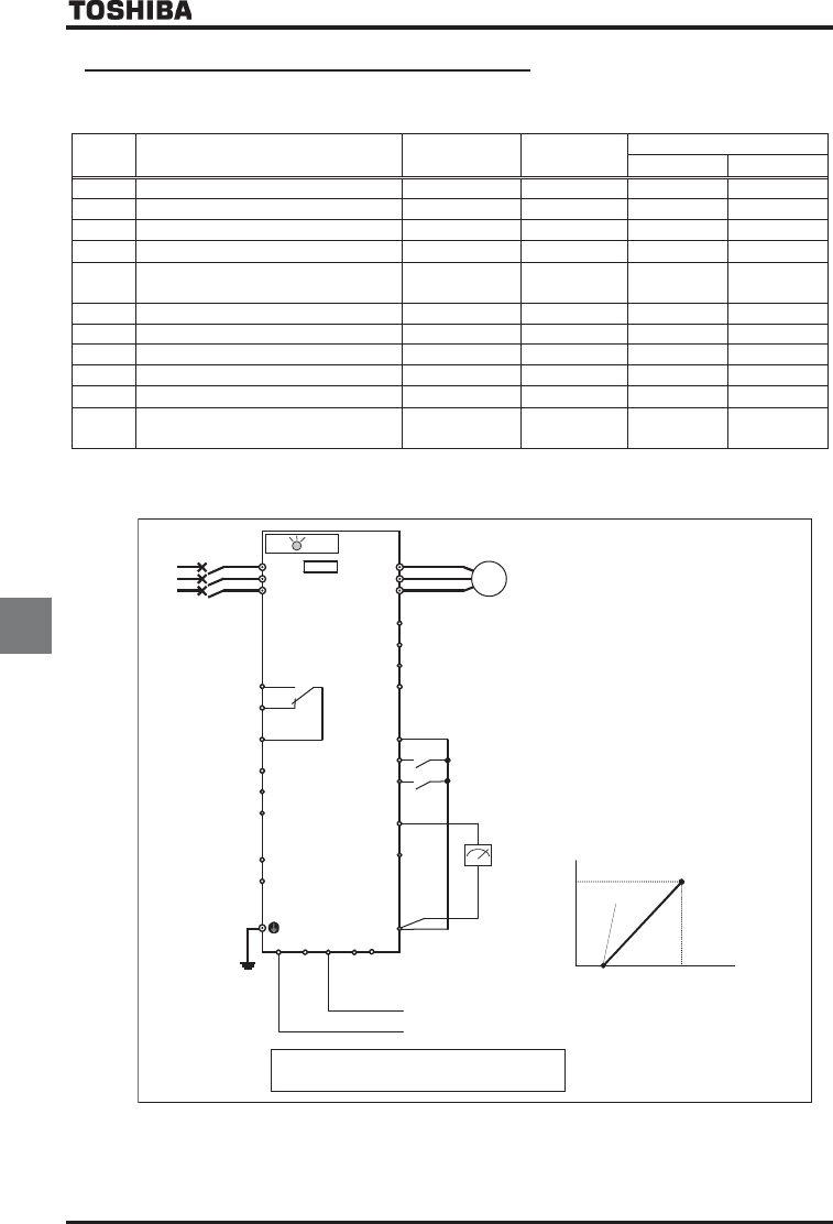
7.3.2 Setup by analog input signals (VI/II terminal)
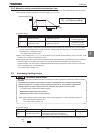
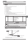
Connect current signal (4 (0) to 20mAdc) or voltage signal (0 to 10Vdc) to the terminal II so that the inverter can be
run and stopped with external commands.
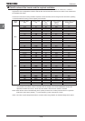
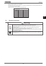
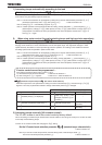
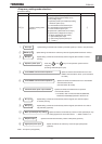
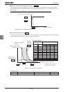
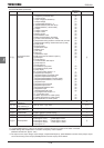
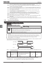
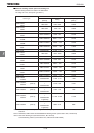
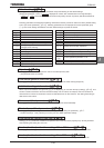
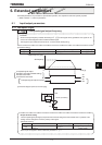
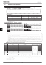
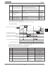
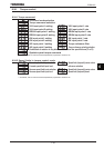
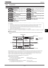
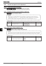
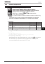
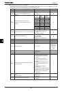
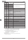
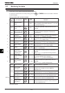
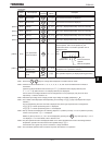
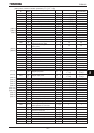
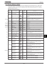
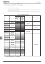
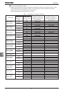
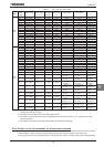
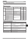
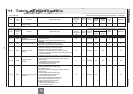
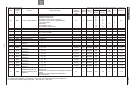
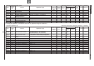
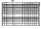
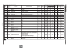
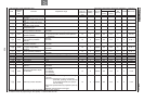
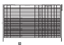
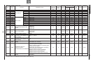
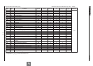
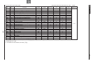
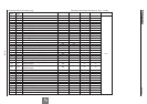
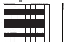
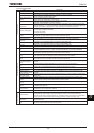
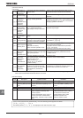
Title Function
Adjustment
range
Default setting
Example of setting
4 (0)~20mAdc 0~10Vdc
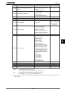
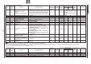
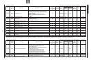
EOQF
Command mode selection ~ (Terminal) (Terminal) (Terminal)
HOQF
Frequency setting mode selection 1 ~ (RR/S4) (
VI/II
) (
VI/II
)
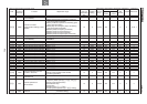
HOUN
FM terminal meter selection ~
HO FM terminal meter adjustment - - - -
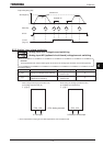
H
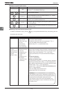
Analog VI/II voltage/current switching
: Voltage input
: Current input
H
Frequency priority selection ,
H
VI/II input point 1 setting ~ %
H
VI/II input point 1 frequency ~HJ Hz
H
VI/II input point 2 setting ~ %
CKH
VI/II input point 2 frequency ~HJ Hz *1 *1 *1
H
Analog input filter
(No filter)~
(Max. filter)
*1: Inverter with a model number ending with -WN, HN: 60.0 -WP: 50.0
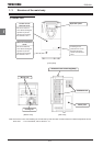
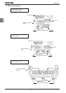
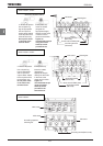
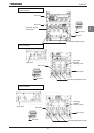
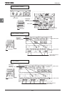
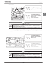
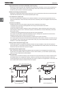
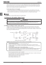
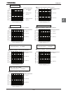
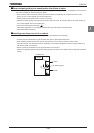
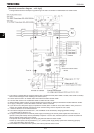
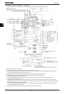
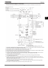
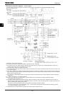
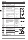
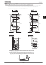
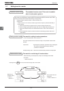
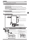
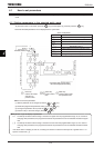
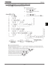
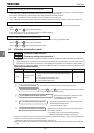
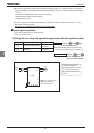
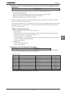
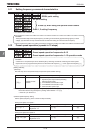
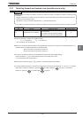
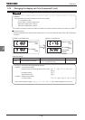
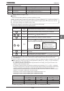
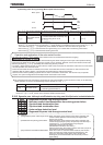
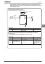
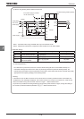
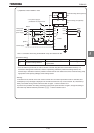
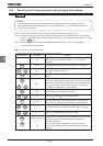
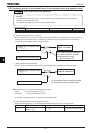
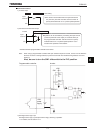
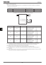
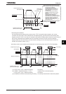
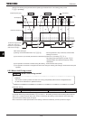
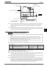
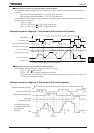
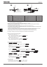
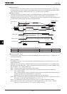
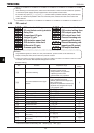
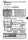
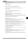
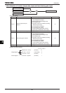
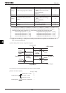
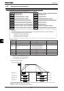
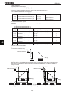
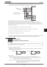
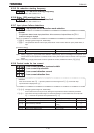
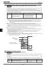
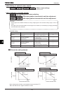
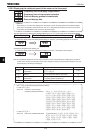
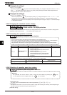
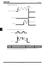
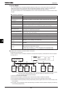
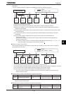
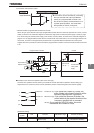
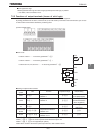
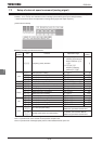
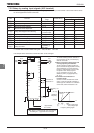
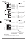
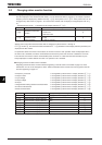
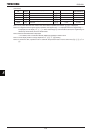
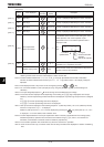
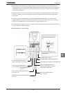
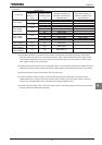
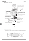
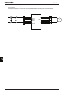
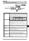
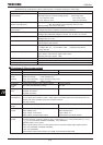
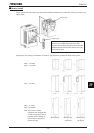
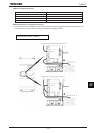
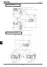
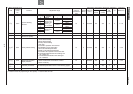
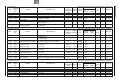
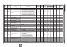
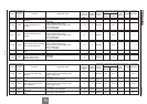
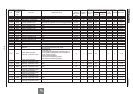
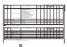
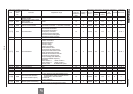
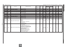
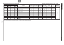
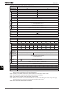
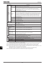
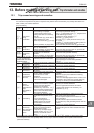
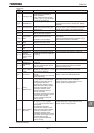
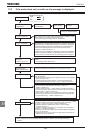
«An example of the connection of terminals: SW1 set to sink logic»
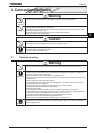
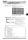
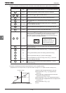
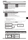
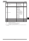
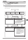
Run/stop setup
To control switching between forward run
(F) and reverse run (R), run and stop by
external commands.
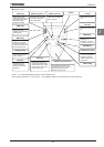
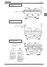
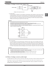
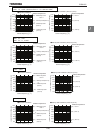
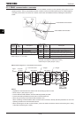
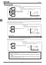
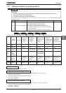
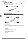
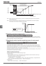
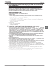
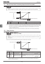
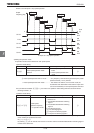
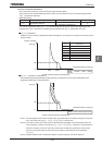
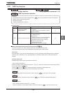
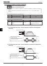
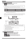
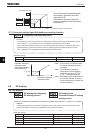
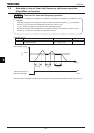
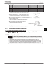
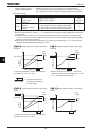
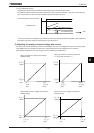
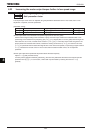
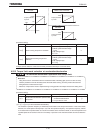
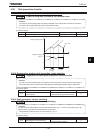
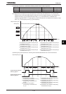
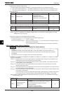
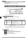
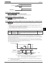
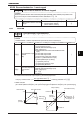
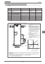
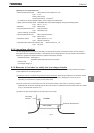
Setup of frequency setting signal and
running frequency characteristic
To set up frequency setting signal to be
input to the external signal (VI/II terminal)
and characteristic of running frequency.
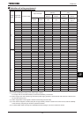
Frequency characteristic is set up at the
two points of VI/II reference point 1
(
H
)/frequency (
H
), VI/II
reference point 2 (H)/frequency
(CKH).
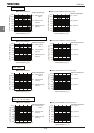
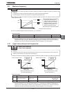
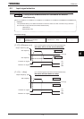
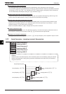
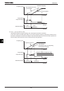
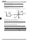
Connection and calibration of
frequency meter
Connect a 1mAdc full-scale DC current
meter, 7.5Vdc full-scale DC voltmeter or
rectifier type AC voltmeter. For calibration
of the meter, refer to the Section 5.16.
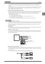
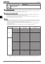
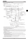
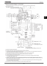
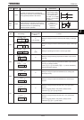
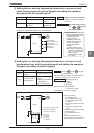
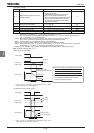
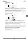
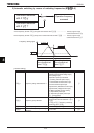
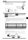
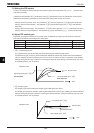
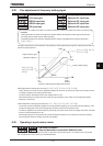
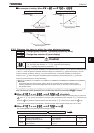
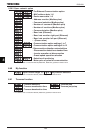
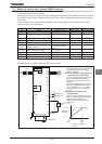
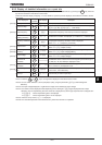
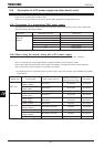
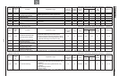
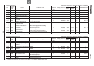
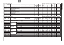
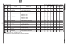
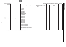
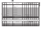
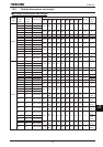
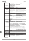
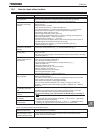
%
CKH
H
H H
Point 2
Point 1
Frequency setting signal
0%
20%
100%
(0 ~ 4 ~ 20mA) current input
(0 ~ 10V) voltage input
Operation
frequency
or 0~10Vdc
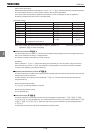
To apply a current
through the VI/II terminal,
the setting of
H
needs to be changed.
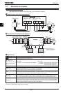
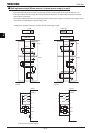
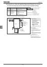
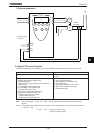
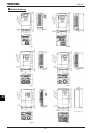
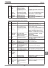
R/L1
U/T1
MCCB
Power
supply
S/L2
T/L3
V/T2
W/T3
CCA RX
CC
FLA
FLB
FLC
P24/PLC
OUT1
VI/II
PP
VF-AS1
meter
NO
RR/S4